Advertisement
Table of Contents
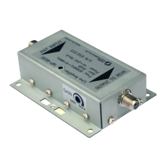
Variable gain Telemetry line amplifier
1. General description
The NP-6030 is a telemetry line amplifier designed for an antenna system used in medical telemetry
applications to overcome line loss between the telemetry antenna and the receiver.
The line amplifier passes power from the output to the input, thus allowing several units to operate with a
single power supply at the receiver.
* To prevent fire or shock hazard, do not expose this device to rain or moisture.
* Use the power supply which provides short circuit protection.
* Don't use too much of amplifier or too much gain. Too much of amplifier may cause self-oscillation or over
input to the receiver.
2. Specifications
1. Frequency range:
2. Gain:
3. Noise Figure:
4. 1 dB compression input
5. Line Power thru coax cable
6. Power requirements:
7. Connector:
8. Power lamp
9. Size:
10. Weight:
11. Operating temperature:
12. Humidity range:
13. Accessories:
For 608 ~ 614 MHz, Model NP-6030
CAUTION
608 to 614 MHz
8 to 36dB Typical
1.5 dB Typical when max gain
91 to 104 dBuEMF Typical
70 mA Typical
+8 to +24 V DC thru coax cable
F-type female 75 ohm
Yes
0.98 (T) x 4.5 (W) x 2.7 (D) inches
0.29 lbs +/- 0.022 lbs
-10 to + 60 degrees C
30 to 95% RH, no condensation
Installation manual
Advertisement
Table of Contents

Summary of Contents for Nissei NP-6030
- Page 1 For 608 ~ 614 MHz, Model NP-6030 1. General description The NP-6030 is a telemetry line amplifier designed for an antenna system used in medical telemetry applications to overcome line loss between the telemetry antenna and the receiver. The line amplifier passes power from the output to the input, thus allowing several units to operate with a single power supply at the receiver.
- Page 2 3. Installation Step 1. Mount the line amplifier on the wall or on a hanging screw in the ceiling with using screws or wire ties. Fig. 1 Wall mounts Fig. 2 Hanging Screw mounts Fig. 3 Gain alignment Wire Tie Screw (Not provided) (Not provided) CAUTION...
Need help?
Do you have a question about the NP-6030 and is the answer not in the manual?
Questions and answers