Table of Contents
Advertisement
Quick Links
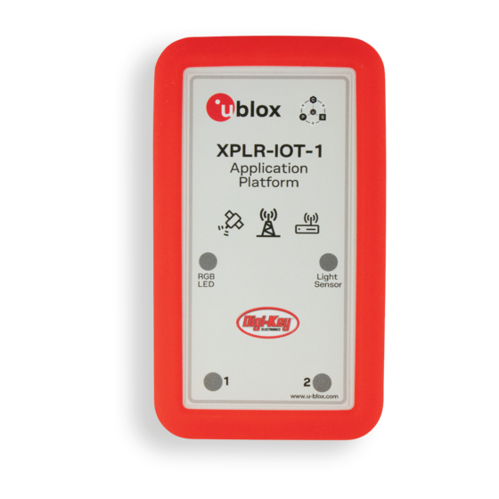
XPLR-IOT-1
Explorer application platform
User guide
Abstract
This document describes the hardware and software architecture and user programming of the
XPLR-IOT-1 application platform. Providing a complete platform for developing various proof-of-
concept IoT applications, the XPLR-IOT-1 showcases products from all u-blox product centers -
including NORA-B106 and NINA-W156 short range radio modules, SARA-R510S cellular modules,
MAX-M10S satellite positioning modules, and the Thingstream IoT service delivery platform.
UBX-21035674 - R02
C1-Public
www.u-blox.com
Advertisement
Table of Contents

Related Manuals for Ublox XPLR-IOT-1

Summary of Contents for Ublox XPLR-IOT-1
- Page 1 This document describes the hardware and software architecture and user programming of the XPLR-IOT-1 application platform. Providing a complete platform for developing various proof-of- concept IoT applications, the XPLR-IOT-1 showcases products from all u-blox product centers - including NORA-B106 and NINA-W156 short range radio modules, SARA-R510S cellular modules, MAX-M10S satellite positioning modules, and the Thingstream IoT service delivery platform.
-
Page 2: Document Information
XPLR-IOT-1 - User guide Document information Title XPLR-IOT-1 Subtitle Explorer application platform Document type User guide Document number UBX-21035674 Revision and date 20-Jun-2022 Disclosure restriction C1-Public Product status Corresponding content status In development / Objective specification Target values. Revised and supplementary data will be published later. -
Page 3: Table Of Contents
XPLR-IOT-1 - User guide Contents Document information ..........................2 Contents ................................3 Product description ..........................5 1.1 Kit includes ..............................6 Hardware architecture ......................... 7 Platform description ..........................8 3.1 PCBA ................................8 3.1.1 PCBA component side ........................9 3.1.2 PCBA antenna ...........................10 3.2 Power and reset subsystem ........................10... - Page 4 XPLR-IOT-1 - User guide 6.1 NORA-B1 ..............................35 Appendix ..............................36 A.1 Glossary ...............................36 Regulatory limitations ........................37 Related documentation ........................... 38 Revision history ............................39 Contact ................................39 UBX-21035674 - R02 Contents Page C1-Public...
-
Page 5: Product Description
XPLR-IOT-1 - User guide 1 Product description The XPLR-IOT-1 IoT application platform allows developers to evaluate and explore the combined synergy of u-blox short-range radio, positioning, and cellular products in a single device. Packaged within a silicone protective bumper, XPLR-IOT-1 comprises a Printed Circuit Board Assembly (PCBA) and rechargeable battery that allows portable operation. -
Page 6: Kit Includes
[10], m-center [11], and u-center [12], may be used when the connection to NORA-B1 is not active. XPLR-IOT-1 also includes an accelerometer, gyroscope, magnetometer (each is 3-axis), battery, state-of-charge gauge, and temperature, humidity, and ambient light sensors. A Qwiic-compatible expansion port allows connection of other I2C devices. -
Page 7: Hardware Architecture
Power, buttons, indicators Power switch, battery, charging circuit, user input and output Table 1: Technology color coding The XPLR-IOT-1 hardware design is available in PDF and Altium formats from the XPLR-IOT-1 GitHub XPLR-IOT-1 hardware repository [1]. UBX-21035674 - R02 Hardware architecture... -
Page 8: Platform Description
3 Platform description Figure 3 provides a transparent view of the XPLR-IOT-1 with the location and orientation of the PCBA shown in relation to the product case. The component side of the PCBA faces the rear of the case, while the antenna side of the PCBA faces the front. -
Page 9: Pcba Component Side
XPLR-IOT-1 - User guide 3.1.1 PCBA component side The component side of the PCBA faces the rear of the case. Figure 4 shows the locations of components on the board. Figure 4: PCBA component side part locations – detailed view... -
Page 10: Pcba Antenna
Figure 5: PCBA antenna side part locations 3.2 Power and reset subsystem XPLR-IOT-1 is powered over USB through a micro-B connector. VBUS is filtered and connected to a Li-Po battery charger. The charger allows a maximum of 500 mA to be drawn from the upstream USB host or hub, which is the high-power limit for a USB 2.0 peripheral. -
Page 11: Power And Charging Status
⚠ Disconnect and remove battery from the PCBA before performing any soldering operations. ⚠ When first using XPLR-IOT-1, connect it to a USB host or a USB power supply to fully charge the battery after shipment. 3.2.1 Power and charging status The bi-color LED, D29, shows power and charging status of XPLR-IOT-1. -
Page 12: Power And Current Measurement
XPLR-IOT-1 - User guide 3.2.3 Power and current measurement System current from the VBAT supply rail is measured by cutting jumper NC15 and placing an ammeter or power analyzer across J10, pins 2 and 3, as shown in Figure 6. -
Page 13: System Reset
System reset can be isolated from each module by cutting the associated jumper, noted in Table This can be useful to independently reset each major component when developing applications. See also the XPLR-IOT-1 schematic in the XPLR-IOT-1 GitHub XPLR-IOT-1 repository [1]. Module or IC Reset isolation jumper... -
Page 14: Serial Subsystem
XPLR-IOT-1 - User guide 3.3 Serial subsystem The Serial subsystem within XPLR-IOT-1 provides a flexible scheme that allows either a PC host or NORA-B1 to connect to each of the modules through software control. Figure 8 shows the USB and serial port subsystem connections. Blue lines indicate USB connections. -
Page 15: U-Blox Modules
Abracon, LLC for Bluetooth in the 2.4 GHz ISM band [18]. NORA-B1 is powered when the Power Switch is on. 3.4.1.1 GPIO assignments NORA-B1 is the central processor of XPLR-IOT-1. Its GPIO signals are used for communication and control of the other u-blox modules, sensors, and interfaces. GPIO Signal Direction Description P0.00 XL1... - Page 16 XPLR-IOT-1 - User guide GPIO Signal Direction Description P0.28 NORA_BTN2 Application button 2 P0.29 DSR6 System UART6, DSR flow control P0.30 CTS6 System UART6, CTS flow control P0.31 TX6 System UART6, TX data P1.00 ALT_INT Sensor interrupt input, ambient light sensor default P1.01 SARA_INT/NINA_SW1...
- Page 17 XPLR-IOT-1 - User guide The other u-blox modules are pre-loaded with u-blox AT command firmware and can be updated with u-blox provided firmware updates over the respective UART connections. 3.4.1.3 Current measurements Current flowing into NORA-B1 from the 3V3 supply rail is measured by cutting jumper NC9 and...
-
Page 18: Nina-W156 - Short Range
XPLR-IOT-1 - User guide 3.4.2 NINA-W156 – short range NINA-W156 provides Wi-Fi connectivity through its UART and u-connectXpress AT command set. Wi-Fi is one method of providing a network connection that is available for sending MQTT messages through Thingstream to process environmental data. NINA-W156 also contains a Abracon Niche antenna for Wi-Fi in the 2.4 GHz ISM band. - Page 19 XPLR-IOT-1 - User guide Figure 13 shows the current measurement location for the NINA-W15 module on the PCBA. See Table 3 for expected current measurements. Figure 13: NINA-W15 module and current measurement Table 8 descirbes the power and LED states for the NINA-W15 module.
-
Page 20: Sara-R510S - Cellular
XPLR-IOT-1 - User guide Table 10 describes the SWITCH_1 and SWITCH_2 signals that are connected to pushbutton switches and control signals from NORA-B1. This allows NINA-W15 system functions, as described in the data sheet and system integration manual. NINA-W15 pin... - Page 21 XPLR-IOT-1 - User guide 3.4.3.1 SARA-R5 power supply and current measurement To measure the current flowing into SARA-R5 from the VBAT supply rail, cut jumper NC6 and place an ammeter or power analyzer across J3, pins 2 and 3, as shown in Figure ⚠...
-
Page 22: Max-M10S - Positioning
XPLR-IOT-1 - User guide Table 11 shows the power and LED states for the NINA-W15 module. Signal State SARA-R5 status LED state NORA_EN_SARA High Powered Not powered Table 11: NINA-W15 power states SARA-R5 power is normally controlled by the GPIO signal NORA_EN_SARA. SARA-R5 can be configured to be always on when the power switch is on by shorting jumper NO1. - Page 23 XPLR-IOT-1 - User guide Figure 17 shows the location of the GNSS antenna. An I2C connection between SARA-R5 and MAX-M10 provides direct communication between the two modules without involving NORA. Figure 17: GNSS antenna 3.4.4.1 GNSS receive path MAX-M10 is connected to the receive antenna through one of two paths – a straight-connection or through a SAW/LNA/SAW combination.
- Page 24 XPLR-IOT-1 - User guide Current flowing into MAX-M10 from the VCC_MAX (3.0 VDC) supply rail is measured by cutting jumper NC13 and placing an ammeter or power analyzer across J6, pins 2 and 3, as shown in Figure 19. See Table 3 for the expected current measurements.
-
Page 25: I2C Sensors
3.5.4 Gyroscope A FXAS21002 gyroscope from NXP Semiconductor senses yaw, pitch, and roll of the XPLR-IOT-1. Full scale ranges are adjustable from ±250°/s. to ±2000°/sec. An optional interrupt may be connected to NORA-B1 by soldering across the jumper NO5 and cutting jumper NC7. On the I2C bus, it is assigned address 0x20. -
Page 26: Ambient Light Sensor
3.5.6 Battery gauge A BQ27421YZFR-G1A battery gauge is included with XPLR-IOT-1 to monitor the charge state of the internal Li-Po battery. Measurements for battery capacity (mAh), state-of-charge (%), and battery voltage (mV) are available. A low battery indicator is connected to an interrupt input of NORA-B1. On the I2C bus, it is assigned address 0x55. -
Page 27: Test Points
XPLR-IOT-1 - User guide Figure 23 shows the NFC circuit connections. Figure 23: NFC connection 3.7 Test points The PCBA includes test points throughout the layout to facilitate system monitoring and application debugging. Table 16 describes the test points. Figure 24 shows the test point locations. - Page 28 XPLR-IOT-1 - User guide Test point Signal Description TP30 3.3 VDC nominal power rail, source = V_BAT through U8 TP31 BATTERY Li-Po battery, positive terminal TP32 ALT_ING Ambient light sensor interrupt TP33 MAX_TXD MAX-M10 UART, TX data TP34 3V3_HUB 3.3 VDC nominal power rail, source = 3V3 when VBUS is present...
- Page 29 XPLR-IOT-1 - User guide Figure 24 shows all test point locations. All test points are on the component side of the PCBA. Figure 24: Test point locations UBX-21035674 - R02 Platform description Page 29 of 39 C1-Public...
-
Page 30: Jumpers
XPLR-IOT-1 - User guide 3.8 Jumpers The PCBA includes several jumpers to select features and for current measurement. Normally open jumpers can be closed by creating a solder bridge across the terminals. Description Remarks Normally open solder jumper SARA-R5 power... -
Page 31: Usb Connection
XPLR-IOT-1 - User guide 4 USB connection ☞ Before plugging in XPLR-IOT-1 the first time, install the USB-UART device drivers. The drivers only need to be installed once on a host PC. Download the device drivers from the GitHub XPLR-IOT-1 hardware repository [5]. - Page 32 XPLR-IOT-1 - User guide Figure 26 shows s-center [10], m-center [11], and u-center [12] connected to the respective VCPs on XPLR-IOT-1. Figure 26: XPLR-IOT-1 communicating with s-center, m-center, and u-center UBX-21035674 - R02 USB connection Page 32 of 39 C1-Public...
-
Page 33: Module Firmware Updates
The application on NORA-B1 can be updated through the MCUboot bootloader over UART. Each new image is uploaded to the XPLR-IOT-1 QSPI flash prior to writing it to the NORA-B1 flash. Download the new application core and network core firmware images from the XPLR-IOT-1 GitHub XPLR-IOT-1 software repository [2]. -
Page 34: Sara-R5
SARA-R5 may be updated over the USB-UART interface. The module must first be enabled through the application. Follow the instructions at USB connection to connect XPLR-IOT-1 to a host PC running Windows. Open a terminal program, such as Putty [29] or TeraTerm [30], to the virtual COM port (VCP) for NORA-B1 (interface 0) with the settings 115,200 bps, no parity, 8 data bits, 1 stop bit. -
Page 35: Application Development
6.1 NORA-B1 The sensor aggregation demonstration and bootloader example code programmed at the factory on XPLR-IOT-1 can be used as a starting point for custom application development. The source code is located at the u-blox GitHub repository and developed using the Nordic Semiconductor nRF Connect SDK (NCS) [31]. -
Page 36: A Appendix
XPLR-IOT-1 - User guide A Appendix A.1 Glossary Abbreviation Definition Arm (Advanced RISC Machines) Holdings Battery Protection System Central Processing Unit Direct Current eSIM Embedded Subscriber Identity Module GNSS Global Navigation Satellite System GPIO General Purpose Input / Output Global Positioning System... -
Page 37: B Regulatory Limitations
XPLR-IOT-1 - User guide B Regulatory limitations XPLR-IOT-1 is an application development platform. It has not been RF certified with worldwide agencies. It may not be offered for sale as an end-user product. XPLR-IOT-1 contains the modules described in Table... -
Page 38: Related Documentation
XPLR-IOT-1 - User guide Related documentation [1] XPLR-IOT-1 GitHub XPLR-IOT-1 hardware repository [2] XPLR-IOT-1 GitHub XPLR-IOT-1 software repository [3] XPLR-IOT-1 Getting Started guide Bootloader Manager [5] Silicon Laboratories USB-UART device drivers [6] NORA-B1 data sheet, UBX-20027119 [7] NORA-B1 system integration manual,... -
Page 39: Revision History
XPLR-IOT-1 - User guide Revision history Revision Date Name Comments 01-Jun-2022 brec Initial release 20-Jun-2022 brec Added Application development chapter. Revised formatting and related references in the block diagram, serial subsystem, and PCBA images. Other minor editorial changes. Contact For further support and contact information, visit us at www.u-blox.com/support.
Need help?
Do you have a question about the XPLR-IOT-1 and is the answer not in the manual?
Questions and answers