Table of Contents
Advertisement
Quick Links
TECHNICAL & SERVICE MANUAL
KS3082 + C3082
KS3682 + C3682
DC INVERTER SPLIT SYSTEM AIR CONDITIONER
Indoor Model No.
KS3082
KS3682
IMPORTANT
These air conditioners employ new
refrigerant R410A.
Pay special attention when
servicing the unit.
Product Code No.
1 852 354 30
1 852 354 31
Indoor Unit
KS3082
KS3682
Outdoor Model No.
Product Code No.
C3082
1 852 354 34
C3682
1 852 354 35
Outdoor Unit
C3082
C3682
FILE NO.
Destination: North America
SM
700859
REFERENCE NO.
Advertisement
Chapters
Table of Contents
Troubleshooting

Subscribe to Our Youtube Channel
Related Manuals for Sanyo C3082


Summary of Contents for Sanyo C3082
- Page 1 TECHNICAL & SERVICE MANUAL KS3082 + C3082 KS3682 + C3682 DC INVERTER SPLIT SYSTEM AIR CONDITIONER Indoor Model No. KS3082 KS3682 Indoor Unit KS3082 KS3682 IMPORTANT These air conditioners employ new refrigerant R410A. Pay special attention when servicing the unit.
-
Page 2: Safety Precautions
Before performing an overhaul, disconnect the power plug or power cable from the unit. Performing the work with the power supplied to the unit, may cause an electric shock. When repair work or circuit inspection that requires power supply for the air conditioner, is to be performed, do not touch the charging section. - Page 3 If a child swallows a battery, make sure that the child gets immediate medical attention. Do not wash the air conditioner with water, as this may cause an electric shock or fire. For the repair work in places with high humidity or moisture, make sure to ground the unit.
-
Page 4: Table Of Contents
SAFETY PRECAUTIONS TABLE OF CONTENTS 1. OPERATING RANGE 2. SPECIFICATIONS 2-1. Unit Specifications 2-2. Major Component Specifications 2-3. Other Component Specifications 3. DIMENSIONAL DATA 4. REFRIGERANT FLOW DIAGRAM 4-1. Refrigerant Flow Diagram 5. PERFORMANCE DATA 5-1. Temperature Charts 5-2. Cooling Capacity 5-3. - Page 5 9. CHECKING ELECTRICAL COMPONENTS 9-1. Measurement of Insulation Resistance 9-2. Checking Continuity of Fuse on PCB Ass'y 10. REFRIGERANT R410A: SPECIAL PRECAUTIONS WHEN SERVICING UNIT 10-1. Characteristics of New Refrigerant R410A 10-2. Checklist before Servicing 10-3. Tools Specifically for R410A 10-4.
-
Page 6: Operating Range
1. OPERATING RANGE Temperature Maximum Cooling Minimum Indoor Air Intake Temp. Outdoor Air Intake Temp. 95 °F D.B. / 71 °F W.B. 115 °F D.B. 67 °F D.B. / 57 °F W.B. 0 °F D.B. -
Page 7: Specifications
2. SPECIFICATIONS 2-1. Unit Specifications KS3082 Indoor Unit C3082 Outdoor Unit Voltage Rating Total Capacity Sensible Capacity Latent Capacity Air Circulation (High) Moisture Removal (High) Available Voltage Range Running Amperes Power Input Power Factor SEER Compressor Locked Rotor Amperes Fuse or Circuit Breaker Capacity... - Page 8 KS3082 Indoor Unit C3082 Outdoor Unit Voltage Rating Total Capacity Sensible Capacity Latent Capacity Air Circulation (High) Moisture Removal (High) Available Voltage Range Running Amperes Power Input Power Factor SEER Compressor Locked Rotor Amperes Fuse or Circuit Breaker Capacity Controls / Temperature Control...
- Page 9 KS3682 Indoor Unit C3682 Outdoor Unit Voltage Rating Total Capacity Sensible Capacity Latent Capacity Air Circulation (High) Moisture Removal (High) Available Voltage Range Running Amperes Power Input Power Factor SEER Compressor Locked Rotor Amperes Fuse or Circuit Breaker Capacity Controls / Temperature Control Control Unit Timer Fan Speeds...
- Page 10 KS3682 Indoor Unit C3682 Outdoor Unit Voltage Rating Total Capacity Sensible Capacity Latent Capacity Air Circulation (High) Moisture Removal (High) Available Voltage Range Running Amperes Power Input Power Factor SEER Compressor Locked Rotor Amperes Fuse or Circuit Breaker Capacity Controls / Temperature Control Control Unit Timer Fan Speeds...
-
Page 11: Major Component Specifications
2-2. Major Component Specifications 2-2-1. Indoor Unit KS3082 Indoor Unit Control PCB Part No. Controls Control Circuit Fuse Remote Control Unit Type Q'ty ... Dia. and Length Fan Motor Type Model ... Q'ty No. of Poles Rough Measure RPM (Cool) Nominal Output Coil Resistance (Ambient Temp. - Page 12 KS3682 Indoor Unit Control PCB Part No. Controls Control Circuit Fuse Remote Control Unit Type Q'ty ... Dia. and Length Fan Motor Type Model ... Q'ty No. of Poles Rough Measure RPM (Cool) Nominal Output Coil Resistance (Ambient Temp. 68 °F (20 °C)) Safety Device Type Over-Current Protection...
- Page 13 2-2-2. Outdoor Unit C3082 Outdoor Unit P.C.Board Part No. Controls Circuit Fuse Compressor Type Compressor Model / Nominal Output Compressor Oil ... Amount Coil Resistance (Ambient Temp. 77 °F (25 °C)) Safety Device CT (Peak current cut-off control) Compressor Discharge Temp. Control Operation cut-off control in abnormal ambient Temp.
- Page 14 C3682 Outdoor Unit P.C.Board Part No. Controls Circuit Fuse Compressor Type Compressor Model / Nominal Output Compressor Oil ... Amount Coil Resistance (Ambient Temp. 77 °F (25 °C)) Safety Device CT (Peak current cut-off control) Compressor Discharge Temp. Control Operation cut-off control in abnormal ambient Temp. Overload Relay Run Capacitor Crankcase Heater...
-
Page 15: Other Component Specifications
2-3. Other Component Specifications KS3082 Indoor Unit KS3682 Outdoor Unit C3082 C3682 • Indoor air temp sensor (Model:KTEC-35-S121-1) (10) (15) (20) (25) (30) (35) (40) Temperature • Indoor heat exchanger sensor (Model:PTM-D51H-S6-1) • Compressor temp sensor (Model:TKS335B) 32 50 68 86 104 122 140 158 176 194 (0) (10) (20) (30) (40) (50) (60) (70) (80) (90) °F... -
Page 16: Dimensional Data
3. DIMENSIONAL DATA KS3082 Indoor Unit KS3682 5-9/16 1-9/32 2-3/4 7-23/32 4-9/16 2-11/16 4-9/16 (300) 11-13/16 2-3/4 5/16 2-3/8 1-15/32 1-7/8 23/32 1-7/8 11-13/16 Unit: inch(mm) (852-0-0010-19600-0) - Page 17 Outdoor Unit C3082 C3682 16-5/32 14-31/32 (340) 13-3/8 13/32 1-1/32 11-13/32 21/32 31/32 19/32 1-3/16 1-27/32 14-11/32 13-9/32 1-3/16 1-27/32 (910) 35-13/16 4-3/4 6-23/32 1-15/16 2-25/32 4-11/32 4-11/32 1-15/16 2-25/32 23/32...
-
Page 18: Refrigerant Flow Diagram
4. REFRIGERANT FLOW DIAGRAM 4-1. Refrigerant Flow Diagram KS3082 Indoor Unit KS3682 Indoor unit Outdoor Unit C3082 C3682 Outdoor unit Wide tube service Wide tube valve Accumulator Muffler 5/8" (15.88 mm) Narrow tube service Narrow tube valve Strainer O.D. 3/8"... -
Page 19: Performance Data
5. PERFORMANCE DATA 5-1. Temperature Charts KS3082 Indoor Unit Outdoor Unit C3082 Cooling Characteristics (RH : 46%, Indoor fan speed : High fan) (60Hz, 230V) (1) Low pressure performance chart (1.2) (1.1) (1.0) (0.9) (0.8) (0.7) (-20) (-15) (-10) (2) Operating current performance chart... - Page 20 KS3682 Indoor Unit Outdoor Unit C3682 Cooling Characteristics (RH : 46%, Indoor fan speed : High fan) (60Hz, 230V) (1) Low pressure performance chart (1.2) (1.1) (1.0) (0.9) (0.8) (0.7) (-20) (-15) (-10) (2) Operating current performance chart (-20) (-15) (-10) (3) Indoor discharge air performance chart 64.4 (18)
-
Page 21: Cooling Capacity
5-2. Cooling Capacity : KS3082 Indoor Unit Outdoor Unit : C3082 Power Supply : 230V Single Phase 60Hz < Cooling Capacity (Low Ambient) > RATING CAPACITY: INDOOR ENT. TEMP. W.B. D.B. 72 (22.2) 76 (24.4) (15.0) 80 (26.7) 84 (28.9) 88 (31.1) - Page 22 < Cooling Capacity > RATING CAPACITY: 30,600 BTU/h INDOOR ENT. TEMP. W.B. D.B. (18.3) 30,650 72 (22.2) 21,390 76 (24.4) 23,710 (15.0) 80 (26.7) 26,280 84 (28.9) 28,610 88 (31.1) 30,650 31,580 72 (22.2) 18,330 76 (24.4) 20,660 (17.2) 80 (26.7) 23,100 84 (28.9) 25,430...
- Page 23 : KS3682 Indoor Unit Outdoor Unit : C3682 Power Supply : 230V Single Phase 60Hz < Cooling Capacity (Low Ambient) > RATING CAPACITY: INDOOR ENT. TEMP. W.B. D.B. 72 (22.2) 76 (24.4) (15.0) 80 (26.7) 84 (28.9) 88 (31.1) 72 (22.2) 76 (24.4) (17.2) 80 (26.7)
- Page 24 : KS3682 Indoor Unit Outdoor Unit : C3682 Power Supply : 230V Single Phase 60Hz < Cooling Capacity > RATING CAPACITY: INDOOR ENT. TEMP. W.B. D.B. 72 (22.2) 76 (24.4) (15.0) 80 (26.7) 84 (28.9) 88 (31.1) 72 (22.2) 76 (24.4) (17.2) 80 (26.7) 84 (28.9)
-
Page 25: Air Throw Distance Charts
5-3. Air Throw Distance Charts KS3082 Indoor Unit Room air temp. : Cooling Fan speed 80°F (26.7°C) High Horizontal distance (ft.) : Flap angle 0 , : Axis air velocity 0 : Flap angle 0 , : Axis air velocity 0 : Flap angle 30 , : Axis air velocity 30 : Flap angle 30 ,... - Page 26 KS3682 Indoor Unit Room air temp. : Cooling Fan speed 80 °F (26.7 °C ) High Horizontal distance (ft.) : Flap angle 0 , : Axis air velocity 0 : Flap angle 0 , : Axis air velocity 0 : Flap angle 30 , : Axis air velocity 30 : Flap angle 30 , : Axis air velocity 30...
-
Page 27: Electrical Data
6. ELECTRICAL DATA 6-1. Electrical Characteristics KS3082 Indoor Unit Outdoor Unit C3082 (1) Voltage:230V Cooling Performance at Rating conditions Running amp. Power input Rating conditions: Indoor air temperature: Outdoor air temperature: (2) Voltage:208V Cooling Performance at Rating conditions Running amp. - Page 28 KS3682 Indoor Unit Outdoor Unit C3682 (1) Voltage:230V Cooling Performance at Rating conditions Running amp. Power input Rating conditions: Indoor air temperature: Outdoor air temperature: (2) Voltage:208V Cooling Performance at Rating conditions Running amp. Power input Rating conditions: Indoor air temperature: Outdoor air temperature: Indoor Unit Fan Motor...
-
Page 29: Electric Wiring Diagrams
6-2. Electric Wiring Diagrams KS3082 Indoor Unit KS3682 GRN/YEL EVAPORATOR FLAP MOTOR PL ELEC J-B FAN MOTOR AC IN COM SI FLAP 5P (WHT) LAMP 9P( WHT ) GRN/YEL 2P(WHT) CONTROLLER COIL 4P( WHT ) 7P(BLU) ROOM/UV 4P ( WHT ) S-LINK (RAC) 4P (BLU) 6P (BLU) - Page 30 Outdoor Unit C3082 C3682 t° GRN/YEL GRN/YEL PRESSURE HIGH t° THERMISTOR OUTDOOR t° THERMISTOR COMPRESSOR t° THERMISTOR COIL 8FA2-5250-71800-1...
-
Page 31: Functions
7. FUNCTIONS 7-1. Operation Functions Emergency operation Emergency operation is available when the remote controller malfunctions, has been lost, or otherwise cannot be used. To operate the system, press the OPERATION button, which is also used as the receiver, below the unit display. Each time this button is pressed, the OPERATION lamp changes color to indicate the type of operation. -
Page 32: Night Setback
The main unit display lamp also becomes dimmer. COOL and DRY modes When the night setback mode is selected, the air conditioner automatically raises the temperature setting 2°F(1°C) when 30 minutes have passed after the selection was made, and then another 2°F(1°C) after another 30 minutes have passed,... - Page 33 Noise Reducing Control (Outdoor Unit) The noise reducing control is the function used for silent operation of the air conditioner by means of setting the dip switch on the outdoor unit P.C.Board to control the fan and compressor's motor speed.
- Page 34 Maximum Current Value Change Function The maximum current value is changed to 14A (for C3082) or 17A (for C3682) to prevent power breaker tripping. (It is set to 24A when the unit is delivered from the factory.) NOTE 1. When the high load is given (Outside temperature is high in the cooling operation), the capacity is reduced.
-
Page 35: Protective Functions
Area: Further frequency increase is prohibited. When the temperature falls below Point B, prevention of a rise in frequency is released and the air conditioner operates as in area. The compressor will stop if the temperature of the compressor discharge exceeds 248°F(120°C) due to shortage of gas or... -
Page 36: Troubleshooting
Follow the procedure below to perform diagnostics. PROCEDURE After turning on power to the air conditioner, use the remote controller and follow the steps below to execute self-diagnostics. Step 1: Press and hold the remote controller QUIET button and 1 HR TIMER button. -
Page 37: Self-Diagnostics Lamps
(1) Self-diagnostics Lamps INDOOR UNIT Since the indications cover various units, the corresponding parts listed below may not be present in some models. Indication on indoor unit LED Clean Timer Operation Alarm Code F04/F12 F09/ F15 to F18 F08/ F21 to F24 E07/P04/P05 P20/P27 OPERATION... - Page 38 (2) If the self-diagnostics function fails to operate No indicators illuminate and the Check the indoor unit. indoor fan does not rotate. Check the power voltage. Blown Is the fuse blown? Normal Replace the circuit board or the fuse. Replace the controller.
-
Page 39: Checking The Indoor And Outdoor Units
8-3. Checking the Indoor and Outdoor Units (1) Checking the indoor unit Control Use the remote controller to operate the unit in "TEST run" mode. To determine whether the mode is currently in "TEST run" mode, check the 4 indicator lamps on the unit. - Page 40 (3) Serial Communication Error Identification Procedure If the lamps on the main body show the following conditions after the completion of self-diagnostics, a communication error between the indoor unit and outdoor unit might be considered. In such a case, identify the breakdown section by using the following procedure. NOTE Refer to "Method of Self-Diagnostics"...
- Page 41 ( Continued from the previous page A. ) 1. Turn OFF the power and wait until the power lamp (LED) of the outdoor unit controller is turned OFF. 2. Short-circuit between the terminals 2 and 3 on the outdoor unit terminal strip. 1.
- Page 42 (3-2) Alarm Code : E07/P04/P05/P20/P27 Troubleshooting Serial Communication 1. Turn off the power and wait until the power lamp (LED) of the outdoor unit controller is turned OFF. 2. Disconnect the cable from the terminal 3 on the Outdoor unit terminal strip. 1.
-
Page 43: Trouble Diagnosis Of Fan Motor
DC motor will trip and voltage output will stop approximately 1 minute after operation is started. For this reason, to measure the voltage again, turn OFF the unit once using the remote controller, and then start the air conditioner again. [Trouble symptom 1] The fan does not stop when the unit stops. -
Page 44: Outdoor Fan Motor
8-4-2. Outdoor Fan Motor This outdoor DC fan motor contains an internal control PCB. Therefore, it is not possible to measure the coil resistance, and the following procedure should be used to check the motor. Perform the trouble diagnosis by Test Run mode described on Installation Instructions of indoor unit. Important: (A) Turn OFF the power before connecting or disconnecting the motor connectors. -
Page 45: Noise Malfunction And Electromagnetic Interference
8-5. Noise Malfunction and Electromagnetic Interference An inverter A/C operates using pulse signal control and high frequencies. Therefore, it is susceptible to the effects of external noise, and is likely to cause electromagnetic interference with nearby wireless devices. A noise filter is installed for ordinary use, preventing these problems. However, depending on the installation conditions, these effects may still occur. -
Page 46: Checking Electrical Components
9. CHECKING ELECTRICAL COMPONENTS 9-1. Measurement of Insulation Resistance The insulation is in good condition if the resistance exceeds 1M ohm. 9-1-1. Power Supply Cord Clamp the grounding wire of power cord with the lead clip of the insulation resistance tester and measure the resistance by placing a probe on either of the two power wires. -
Page 47: Checking Continuity Of Fuse On Pcb Ass'y
9-2. Checking Continuity of Fuse on PCB Ass'y Remove the PCB Ass'y from the electrical component box. Then pull out the fuse from the PCB Ass'y. (Fig. 5) Check for continuity using a multimeter as shown in Fig. 6. Fuse Fig. -
Page 48: Refrigerant R410A: Special Precautions When Servicing Unit
When refrigerant R410A is used, the composition will differ depending on whether it is in gaseous or liquid phase, and the basic performance of the air conditioner will be degraded if it is charged while the refrigerant is in gaseous state. Thus, always charge the refrigerant while it is in liquid phase. -
Page 49: Checklist Before Servicing
10-2. Checklist before Servicing Use a clutch-type flare tool for R410A or the conventional flare tool. Note that sizes of the resultant flares differ between these two tools. Where a conventional flare tool is used, make sure to observe A Specification (amount of extrusion) by using the flare spacer. -
Page 50: Tools Specifically For R410A
10-3. Tools Specifically for R410A For servicing, use the following tools for R410A Tool Distinction Tools specifically for R410A Tools which can be com- monly used for R22, R407C, and R410A The above tools specifically for R410A must not be used for R22 and R407C. CAUTION Doing so will cause malfunction of the unit. -
Page 51: In Case Of Compressor Malfunction
10-5. In Case of Compressor Malfunction Should the compressor malfunction, be sure to make the switch to a replacement CAUTION compressor as quickly as possible. Use only the tools indicated exclusively for R410A. Specifically for R410A." 10-5-1. Procedure for Replacing Compressor (1) Recovering refrigerant Any remaining refrigerant inside the unit should not be released to the atmosphere, but recovered using the... - Page 52 (5) Recharging Be sure to charge the specified amount of refrigerant in liquid state using the service port of the wide tube service valve. The proper amount is listed on the unit's nameplate. When the entire amount cannot be charged all at once, charge gradually while operating the unit in Cooling Operation.
-
Page 53: In Case Refrigerant Is Leaking
10-6. In Case Refrigerant is Leaking Never attempt to charge additional refrigerant when refrigerant has been leaking CAUTION from the unit. Follow the procedure described below to locate points of leaks and carry out repairs, then recharge the refrigerant. (1) Detecting Leaks Use the detector for R410A to locate refrigerant leak points. -
Page 54: Charging Additional Refrigerant
10-8. Retro-Fitting Existing Systems 10-8-1. Use of Existing Units Never use new refrigerant R410A for existing units which use R22. This will cause the air conditioner to operate improperly and may result in a hazardous condition. 10-8-2. Use of Existing Tubing If replacing an older unit that used refrigerant R22 with a R410A unit, do not use its existing tubing. -
Page 55: Appendix Ainstruction Manual
APPENDIX A INSTRUCTION MANUAL KS3082 + C3082 KS3682 + C3682 (OI-852-6-4181-150-00-0) - Page 56 KS3082 KS3682 COOL/DRY Model This air conditioner uses the new refrigerant R410A. Pub. OI-85264181 © SANYO 2010 INSTRUCTION MANUAL Inverter-Controlled Split System Air Conditioner MODE D’EMPLOI Climatiseur de type séparé contrôlé par inverseur Save These Instructions! Conserver ce mode d’emploi...
-
Page 57: Features
FEATURES This air conditioner is an inverter type unit that automatically adjusts capability as appropriate. Details on these functions are provided below; refer to these descriptions when using the air conditioner. • Microprocessor Controlled Operation The interior compartment of the remote control unit contains several features to facilitate automatic operation, easy logically displayed for easy use. -
Page 58: Product Information
• Do not install the air conditioner where excessively high heat-generating objects are placed. Avoid: To protect the air conditioner from heavy corrosion, avoid installing the outdoor unit where salty sea water can splash directly onto it or in sulphurous air near a spa. OI-150-3-EG... -
Page 59: Names Of Parts
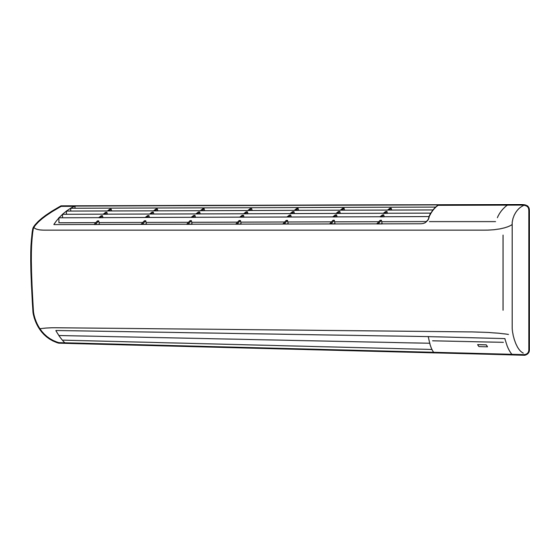
Consequently, the shape may differ from that of the air conditioner which you have selected. This air conditioner consists of an indoor unit and an outdoor unit. You can control the air conditioner with the remote control unit. Air Intake Air from the room is drawn into this section and passes through air filters which remove dust. -
Page 60: Remote Control Unit (Display)
REMOTE CONTROL UNIT (DISPLAY) Displayed when setting temperature (1) Operation mode MILD DRY ... COOL ... FAN ... (2) Fan speed Automatic operation ... HIGH ... MEDIUM... LOW ... (3) Temperature setting 60 – 86 °F When set to 80 °F temperature indication... -
Page 61: Remote Control Unit
REMOTE CONTROL UNIT Transmitter When you press the buttons on the remote control unit, the the display to transmit the setting changes to the receiver in the air conditioner. Display Information on the operating conditions is displayed while the remote control unit is switched on. - Page 62 • The remote control unit sends the temperature signal to the air conditioner regularly at five minute intervals. If the signal from the remote control unit stops for more than 15 minutes due to the loss of the remote control unit or other trouble, the air conditioner will switch to the temperature sensor which is built into the indoor unit and control the room temperature.
-
Page 63: Using The Remote Control Unit
• In direct sunlight • Behind a curtain or other places where it is covered • More than 26 ft.(8 m) away from the air conditioner • In the path of the air conditioner’s airstream • Where it may become extremely hot or cold •... -
Page 64: Operation With The Remote Control Unit
For dehumidifying operation For cooling operation For fan only operation STEP 2 To start the air conditioner, press the ON/ OFF operation button. STEP 3 Press the TEMP. setting buttons to change the temperature setting to the desired temperature. -
Page 65: Night Setback Mode
Pressing the MODE selector button cancels Night Setback mode. In Cooling and DRY Mode: ( When the night setback mode is selected, the air conditioner automatically raises the temperature setting 2 °F when 30 minutes have passed after the selection was made, and then another 2 °F after another 30 minutes have passed, regardless of the indoor temperature when night setback was selected. -
Page 66: Led Clean Mode
• The remote control unit should be used in the location specified in “REMOTE CONTROL UNIT INSTALLATION POSITION” on page 8. • The air conditioner’s stop order (stated in (2) / above) is valid only when the unoccupied function is operated. Status... -
Page 67: Special Remarks
5 minutes of power being restored. Clicking Sound Clicking sound is heard from the air conditioner • In cooling operation, any plastic parts may shrink due to a sudden temperature change. In this event, a clicking sound may occur. This is normal, and the sound will soon disappear. - Page 68 OI-150-13-EG 4. How to set daily ON/OFF repeat timer (Example) To start operation at 7:10 am. and stop the air conditioner at 11:00 am. 10:30 pm. Indication Present time...
-
Page 69: Using The 1-Hour Off Timer
USING THE 1-HOUR OFF TIMER 1. 1-Hour OFF Timer This function causes the unit to operate for one hour and then stop, regardless of whether the unit is on or off when this button is pressed. indicator in the display indicates that this function is operating. -
Page 70: Operation Without The Remote Control Unit
OPERATION button (ON/OFF) If you have lost the remote control unit or it has trouble, follow the steps below. When the air conditioner is not running Each time the OPERATION button is pressed, the operation mode changes cyclically. Cooling operation NOTE The temperature is set to the room temperature minus 4°F during... - Page 71 This air clean filter cannot remove harmful gases or vapors nor ventilate air in the room. You must open doors or windows frequently when you use gas or oil heating appliances. Otherwise there is a risk of suffocation in extreme cases. How to install the air clean filter The air clean filter needs to be installed behind the anti-mold filter.
-
Page 72: Troubleshooting
TROUBLESHOOTING If your air conditioner does not work properly, first check the following points before requesting service. If it still does not work properly, contact your dealer or service center. Trouble Possible Cause Air conditioner does 1. Power failure. not run at all. -
Page 73: Appendix B Installation Instructions
APPENDIX B INSTALLATION INSTRUCTIONS KS3082 + C3082 KS3682 + C3682 (II-852-6-4190-499-00-0) -
Page 74: Installation Instructions
NOTE The illustrations are based on the typical appearance of a standard model. Consequently, the shape may differ from that of the air conditioner that you are installing. SANYO North America Corporation Commercial Solutions Division 2055 Sanyo Ave., San Diego CA 92154, U.S.A. -
Page 75: Important
Get a partner to help, and bend your knees when lifting to reduce strain on your back. Sharp edges or thin alu- minum fins on the air conditioner can cut your fingers. When Installing… …In a Ceiling or Wall Make sure the ceiling/wall is strong enough to hold the unit’s weight. -
Page 76: General
1. General This booklet briefly outlines where and how to install the air conditioning system. Please read over the entire set of instructions for the indoor and outdoor units and make sure all accessory parts listed are with the system before beginning. -
Page 77: Additional Materials Required For Installation
To prevent abnormal heat genera- WARNING tion and the possibility of fire, do not place obstacles, enclosures and grilles in front of or surround- ing the air conditioner in a way that may block air flow. AVOID: direct sunlight. ●... -
Page 78: Outdoor Unit
2-2. Outdoor Unit AVOID: heat sources, exhaust fans, etc. (Fig. 4) ● damp, humid or uneven locations. ● choose a place as cool as possible. ● choose a place that is well ventilated. ● install in a location where at least two sides are unob- ●... - Page 79 2-2-1. Installing the Unit in an Area with High Winds and in a Snowy Area ● In locations with high winds, a wind-proof duct should be fitted and direct exposure to the wind should be avoided as much as possible. (Fig. 5e) ●...
- Page 80 2-2-3. Dimensions of Wind-proof Duct Reference diagram for C3082/3682 Air Intake Air Intake discharge 6-11/16" 25-31/32" 37-1/32" 2-11/16" 21-25/32" discharge discharge discharge Reference diagram for wind-proof duct (locally purchased): STK-DGV160E 21-25/32" (4-31/32") 11-13/16" Hole for anchor bolt (4-R1/4") / Anchor bolt : 3/8" or M10 discharge (4-11/32")
- Page 81 Required space around the outdoor unit If the wind-proof duct is used, the space shown below must be secured around the outdoor unit. If the unit is used without the required space, a protective device may activate, preventing the unit from operating. (1) Single-unit installation The top and both sides must remain open.
- Page 82 2-2-4. Dimensions of Snow-proof Duct Reference diagram for C3082/3682 27-5/8" Air Intake Air discharge (8-15/16") 25-31/32" 39-1/4" 27-7/32" Reference diagram for snow-proof duct (locally purchased): STK-BDV80E Fastened by screws at 14 locations Fastened by screws 25-13/32" at 3 locations 17-9/16"...
- Page 83 Reference diagram for snow-proof duct Space requirements for setting C3082/3682 with STK-BDV80E [Obstacle to the rear of unit] Top is open: (1) Single-unit installation (2) Obstacles on both sides Min. 11-13/16" or more (3) Multiple-unit installation (2 or more units) Min.
- Page 84 [Obstacles to the front and rear of unit] The top and both sides must remain open. Either the obstacle to the front or the obstacle to the rear must be no taller than the height of the outdoor unit. (1) Single-unit installation (2) Ob stacles on both sides Installation is possible with the maximum 3 outdoor units.
-
Page 85: How To Install The Indoor Unit
3. How to Install the Indoor Unit 3-1. Remove the Rear Panel from the Unit (1) Remove and discard the set screw on the rear panel. (Fig. 6) ▲ (2) Press the 2 marks on the frame cover and disengage the stationary tabs from the frame. -
Page 86: Install The Rear Panel On The Wall
(4) Using a sabre saw, key hole saw or hole-cutting drill attachment, cut a hole in the wall. See Table 4 and Fig. 10. Table 4 Hole Dia. 3-5/32" (80 mm) (5) Measure the thickness of the wall from the inside edge to the outside edge and cut PVC pipe at a slight angle 1/4"... -
Page 87: Removing And Installing The Grille
3-4. Removing and Installing the Grille Basically, these models can be installed and wired with- out removing the grille. If access to any internal part is needed, follow the steps as given below. How to remove the grille (1) Open the front panel until it is nearly horizontal, grasp the sections near the front panel arms on both sides, and then remove the panel by pushing the arms towards the outside while pulling the panel towards... -
Page 88: Shape The Indoor Side Tubing
3-5. Shape the Indoor Side Tubing (1) Arrangement of tubing by direction a) Right or left tubing Cut out the corner of the right/left frame with a hacksaw or the like. (Figs. 20 and 21) b) Right-rear or left-rear tubing In this case, the corner of the frame need not be cut. -
Page 89: Wire Size And Length
Refer to the wiring system diagram (Fig. 23) for the meaning of (A), (B), and (C) in Table 5. Refer to your local codes or in the absence of local codes see the National Electric Code: ANSI/NFPA70. Table 5 Model AWG12 (min.) or bigger (*1) for C3082 Wire Size AWG10 (min.) or bigger (*1) for C3682 C3082... -
Page 90: Wiring Instructions For Inter-Unit Connections
3-8. Wiring Instructions for Inter-unit Connections (1) Insert the inter-unit wiring (according to local codes) into the through-the-wall PVC pipe. Run the wiring toward the indoor side allowing approx. 10" (25 cm) to extend from the wall face. (Fig. 24) (2) Grasp both ends of the front panel, push the arms towards the outside, and remove the front panel by opening it towards the front and pulling it towards... - Page 91 Loose wiring may cause the WARNING terminal to overheat or result in unit malfunction. A fire hazard may also exist. There- fore, be sure all wiring is tightly connected. When connecting each power wire to the corresponding terminal, follow the instructions “How to connect wiring to the terminal”...
-
Page 92: Mounting
3-9. Mounting (1) To install the indoor unit, mount the indoor unit onto the 3 tabs on the upper part of the rear plate. (2) Hold down the air discharge outlet and press the lower part of the indoor unit until it clicks to securely fasten to the 2 tabs on the lower part of the rear plate. - Page 93 ■ Left-side tubing (1) Lead the tubing and drain hose through the wall, allowing sufficient length for connection. Then bend the tubing using a tube bender to make the attach- ment. (Fig. 38) (2) Switch the drain hose and drain cap. Switching drain hose and drain cap (a) Locate the drain hose and the drain cap.
-
Page 94: Frame Fastening Method
5/32" x 13/32" (4 x 10 mm). (Fig. 43) NOTE Under normal conditions, the installation design calls for a less than 3/32" (2 mm) gap between the air conditioner unit and the wall. Confirm that the gap is appropriate (less than 2 mm). 3-11. Drain Hose a) The drain hose should be slanted downward to the outdoors. -
Page 95: How To Install The Outdoor Unit
4. How to Install the Outdoor Unit First refer to Section 2. Installation Site Selection. 4-1. Wiring Instructions for the Outdoor Unit Regulations on wire size differ from locality to locality. For field wiring requirements, please refer to your local elec- trical codes. -
Page 96: Refrigerant Tubing
5. Refrigerant Tubing 5-1. Use of the Flaring Method Many of the conventional split system air conditioners employ the flaring method to connect refrigerant tubes which run between indoor and outdoor units. In this method, the copper tubes are flared at each end and connected with flare nuts. -
Page 97: Connecting Tubing Between Indoor And Outdoor Units
5-4. Connecting Tubing between Indoor and Outdoor Units a) Tightly connect the indoor side refrigerant tubing exten- ded from the wall with the outdoor side tubing. (Fig. 52) b) To fasten the flare nuts, apply specified torque as: Table 6 Tube Dia. -
Page 98: Air Purging
6. Air Purging Air and moisture remaining in the refrigerant system have undesirable effects as indicated below. Therefore, they must be purged completely. pressure in the system rises ● operating current rises ● cooling (or heating) efficiency drops ● moisture in the air may freeze and block capillary tubing ●... - Page 99 (14) If there is no leakage, stop the air conditioner. (15) Wipe off the soap on the tubing. This completes air purging with a vacuum pump and the air conditioner is ready for actual operation.
- Page 100 How to Test Run the Air Conditioner After turning on the power of the air conditioner, use the remote controller and follow the steps below to conduct the test run. (1) Set the remote controller in Test Run mode. (Fig. 59a) a) Press and hold the QUIET button and the 1HR.
-
Page 101: Basic Functions Of The Service Valves
Table 8 Narrow Tube Service Action Valve (2-Way) CLOSED Shipping Fully OPEN Operating and test running the air conditioner Fully OPEN Measuring pressure and gas charging CLOSED Air purging with a vacuum pump CAUTION When opening or clos- ing the service valve... -
Page 102: Service Valve Connections
In direct sunlight ● Behind a curtain or other place where it is covered ● More than 26' (8 m) away from the air conditioner ● In the path of the air conditioner’s airstream ● Where it may become extremely hot or cold ●... -
Page 103: Address Switch
NOTE Once changed, you cannot restore the original address setting of the air conditioner. (1) Switch on the power source. (2) Break the address-setting tab marked “A” on the second remote controller to change the address (Fig. - Page 104 For Parts or Service Assistance please contact your local Sanyo HVAC Contractor or Distributor United States: SCS, HVAC Solutions Canada: Sanyo Canada Inc. Web: www.SanyoHVAC.com Web: www.SanyoHVAC.com Parts: hvac.parts@sna.sanyo.com Parts/Service: hvac@sci.sanyo.com Service: hvac.service@sna.sanyo.com 3/10 Printed in Japan...
Need help?
Do you have a question about the C3082 and is the answer not in the manual?
Questions and answers