
Related Manuals for Campbell AL200


Summary of Contents for Campbell AL200
- Page 1 AL200 ALERT2 Encoder, Modulator, and Sensor Interface 4/14 C o p y r i g h t © 2 0 1 3 - 2 0 1 4 C a m p b e l l S c i e n t i f i c ,...
- Page 3 Limited Warranty “Products manufactured by CSI are warranted by CSI to be free from defects in materials and workmanship under normal use and service for twelve months from the date of shipment unless otherwise specified in the corresponding product manual. (Product manuals are available for review online at www.campbellsci.com.) Products not manufactured by CSI, but that are resold by CSI, are warranted only to the limits extended by the original manufacturer.
- Page 4 SCIENTIFIC, INC., phone (435) 227-9000. After an applications engineer determines the nature of the problem, an RMA number will be issued. Please write this number clearly on the outside of the shipping container. Campbell Scientific’s shipping address is: CAMPBELL SCIENTIFIC, INC.
-
Page 5: Table Of Contents
3. Initial Inspection ............1 4. Quickstart ..............2 Stand-Alone Mode ................2 4.1.1 Physical Setup ................2 4.1.2 Configuring the AL200 ..............2 Datalogger Peripheral Mode ..............3 4.2.1 Physical Setup ................3 4.2.2 Configuring the AL200 ..............3 5. - Page 6 C. LED Indicators ............C-1 D. AL200 Settings ............D-1 E. AL200 USB Driver Installation Instructions ..E-1 F. Updating the Operating System of the AL200 ..F-1 G. List of Recommended Sensor IDs ......G-1 H. Calculating Multipliers and Offsets ....... H-1 Figure 5-1.
-
Page 7: Introduction
Keep RS-232 and CS I/O connections short. The AL200 is NOT powered over CS I/O. • When powered over USB, the AL200 will not power up either the radio or • attached sensors. •... -
Page 8: Quickstart
1. Connect the supplied USB cable between a USB port on your computer and the USB port on the AL200. The AL200 will be powered over the USB for configuration only. The AL200 will not turn on an attached radio and transmit while powered over the USB port. -
Page 9: Datalogger Peripheral Mode
Test Button may be used to trigger a data transmission. Datalogger Peripheral Mode Out of the box, the AL200 is configured for ALERT2 on CS I/O, ALERT Concentration on RS-232 (datalogger peripheral mode). In this mode, the AL200 will receive ALERT protocol packets on the RS-232 port from an external device and retransmit them as ALERT2 packets using the ALERT concentration protocol. -
Page 10: Overview
CR800 or CR1000, or other device and transmit this data during a designated time slot. In both modes, the AL200 will receive ALERT data on one of the serial ports, then concentrate and retransmit the data via the ALERT2 protocol. -
Page 11: Specifications
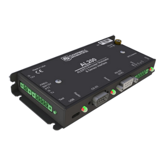
AL200 ALERT2 Encoder, Modulator, and Sensor Interface FIGURE 5-1. AL200 The AL200 includes a CS I/O port and an RS-232 port for serial communications. A USB device port is used for configuring the AL200, viewing real time sensor data, and diagnostics. An SMA female connector is provided for connecting a GPS antenna, and a removable screw terminal allows for the easy connection of an analog radio. -
Page 12: Al200 Dimensions
When used as a datalogger peripheral, the same Device Configuration Utility software is used to configure the AL200. Additional steps will be required to program the datalogger to interface with the AL200. Micro-B receptacle Can power AL200 during configuration;... - Page 13 AL200. Pressing the button for longer than 6 seconds will cause the AL200 to generate a test tone and sustain it for 5 seconds. If the AL200 has been configured as a datalogger peripheral, only the test tone functionality is active.
-
Page 14: Installation
The AL200 is configured via the USB port using the Device Configuration Utility. It is important to have an understanding of the network that the AL200 will be used in. There are many settings that are used to configure when and how the AL200 will report data in the time division multiple access (TDMA) scheme. -
Page 15: Stand-Alone Device
AL200 ALERT2 Encoder, Modulator, and Sensor Interface 3. Under Device Type, select AL200. 4. Click the browse button next to Communication Port and select the port associated with the AL200. 5. Click OK. 6. Click Connect. 7. Specify the settings on each tab as described below for the desired mode. - Page 16 Radio Settings The default radio settings have been chosen to work well with Campbell Scientific’s RF320 series (Ritron DTX-L series) radios. If using a different type of radio, consult the manufacturer and apply the changes to the following settings.
- Page 17 AL200 ALERT2 Encoder, Modulator, and Sensor Interface Set the Sensor Scan Interval – This is how often the AL200 will • power up and measure attached and enabled sensors. Value is expressed in seconds. • Set the SW12 Warm Up Time – This is the amount of time in seconds that the AL200 will wait after powering up attached sensors before making a measurement.
-
Page 18: Datalogger Peripheral
Set the Configuration Sensor Scan Interval – This is the interval on • which sensors will be read only while you are connected to the AL200 with the Device Configuration Utility software. After configuring the AL200 settings, click the Apply button at the bottom of the screen to send the changes to the device. - Page 19 Radio Settings The default radio settings have been chosen to work well with Campbell Scientific’s RF320 series (Ritron DTX-L series) radios. If using a different type of radio, consult the manufacturer and apply the changes to the following settings.
-
Page 20: Mounting In An Enclosure
Connect the sensor leads to the appropriate sensor inputs. Depending on site conditions, additional surge protection for the sensor cables may be required. If using the AL200 as a datalogger peripheral, connect either the CS I/O or RS- 232 port to the datalogger using the supplied SC12 cable. -
Page 21: Maintenance
It is a good idea to periodically check the sensor inputs against known values to ensure that the device is still within the specified accuracy ranges. Connecting to the AL200 with a USB cable will force the AL200 to measure the attached sensors on the Configuration Sensor Scan Interval. This will allow the user to quickly see how sensors respond to changes. -
Page 22: Troubleshooting
13 minutes. 11. Repair The AL200 is designed to give years of trouble-free service with reasonable care. However, if factory repair is needed, first contact a Campbell Scientific application engineer to obtain an RMA (Return Materials Authorization) number. -
Page 23: Glossary
Protocol Data Unit. Data payload with control header used for exchange between protocol layers. Sometimes generalized as “packet”. Synchronous Device Communications. A Campbell Scientific addressable, synchronous communications protocol. The protocol allows multiple peripherals to be connected to the same communication bus as long as each... - Page 24 Appendix A. Glossary...
-
Page 25: Cables And Connector Pin Descriptions
RS-232 is used for asynchronous serial communication. It is a standard EIA/TIA-232 DB9 socket female DCE interface. A DB9 male to male null modem cable (pn 18663) is used to connect the AL200 to a Campbell Scientific datalogger’s RS-232 port. -
Page 26: Usb
Appendix B. Cables and Connector Pin Descriptions B.3 USB The USB interface is a standard Micro-B configuration. A USB A to Micro-B cable is supplied (pn 27555). Connection to a PC requires installation of the FTDI Virtual COM Port (VCP) device driver. TABLE B-3. -
Page 27: Sensor I/O Interface
Appendix B. Cables and Connector Pin Descriptions TABLE B-5. Radio Interface Pin Description Function Freq. Select Frequency Select. Accommodate frequency selection during operation by grounding selected pin on radio interface. SW12V Switchable radio power supply Push-to-talk. Grounded during transmission. Ground Transmit audio output B.6 Sensor I/O Interface The sensor I/O interface is a 5-pin screw terminal. - Page 28 Appendix B. Cables and Connector Pin Descriptions...
-
Page 29: Led Indicators
LEDs will appear orange. Under normal operation, the LED sequence should be as follows from powering up the device through a data transmission: GPS LED is red immediately after power, then flashes green indicating that the AL200 has a GPS fix. - Page 30 Appendix C. LED Indicators b. The GPS light remains red for up 13 minutes as the AL200 downloads leap second information from the satellite. The Serial LED flashes green or red indicating that the AL200 has been sent data from a datalogger, or data is being internally transferred from the sensor inputs to memory.
-
Page 31: Al200 Settings
Operation Mode The AL200 supports ALERT2 and ALERT-concentration processing. Each process can service one physical connection on the AL200 at a time. Those connections are the CS I/O, RS-232, and direct-sensor inputs. The CS I/O port and sensor inputs are multiplexed, so their use is mutually exclusive. - Page 32 For maximum power savings, set to On Only With Data to Tx. The radio will only power up if the AL200 has data to be transmitted. For maximum responsiveness, set to On Every Frame or On Continuously. If On Every Frame, the radio will be turned on for a minimum of Radio Warm Up milliseconds every frame.
- Page 33 Appendix D. AL200 Settings SE1 Mode Sets the operation mode for the SE1 terminal input. SE1 is used for measuring millivolt or milliamp input signals, like those commonly produced by a pressure transducing level sensor. SE1 ALERT2 Sensor ID The ALERT2 sensor ID that will be used to identify a SE1 general sensor report.
- Page 34 Appendix D. AL200 Settings SE1 Transmitted Last three transmitted readings for SE1 (T0, T1, T2). The list will be queried and displayed here at a regular refresh interval. While connected via Device Configuration Utility, automated reporting/transmission is disabled. Press and hold the test button for 3 to 5 seconds to force a transmission while connected.
-
Page 35: Al200 Usb Driver Installation Instructions
Appendix E. AL200 USB Driver Installation Instructions When plugging the AL200 into your Windows XP or Vista PC for the first time, it may be necessary to install the FTDI Virtual COM Port (VCP) driver. This is not required when using Windows 7 or 8. - Page 36 Appendix E. AL200 USB Driver Installation Instructions...
-
Page 37: Updating The Operating System Of The Al200
Appendix F. Updating the Operating System of the AL200 Whenever a new operating system is released for the AL200, it will be available from our website, www.campbellsci.com/downloads. Follow these steps to send the new OS to the AL200: 1. Connect a USB cable between one of your computer’s USB ports and the USB port on the AL200. - Page 38 Appendix F. Updating the Operating System of the AL200...
-
Page 39: List Of Recommended Sensor Ids
Appendix G. List of Recommended Sensor IDs TABLE G-1. Recommended Sensor IDs Sensor Type Rain Air Temperature Relative Humidity Barometric Pressure Wind Speed Wind Direction Peak Wind Speed Stage Battery Voltage *As recommended in the ALERT2 Application Layer Protocol Specification document, Version 1.2. - Page 40 Appendix G. List of Recommend Sensor IDs...
-
Page 41: Calculating Multipliers And Offsets
Appendix H. Calculating Multipliers and Offsets Unlike ALERT which could only represent measurement values between 0 and 2047, ALERT2 has the ability to represent a much larger range of floating point numbers. It is no longer necessary to scale a reading to a unit-less number less than 2047. - Page 42 Appendix H. Calculating Multipliers and Offsets Now, we can calculate pressure based on the reading we get from the sensor. For example, you measure the sensor’s output as 2543.210 mV. Pressure would be determined by: Pressure = (0.0060 • 2543.210) + (–0.074) = 15.263 psi To determine water depth, simply multiply the pressure value by the appropriate conversion factor.
- Page 44 • info@campbellsci.com.cn • info@campbellsci.de www.campbellsci.com www.campbellsci.de Campbell Scientific do Brasil Ltda. (CSB) Campbell Scientific Spain, S. L. (CSL Spain) Rua Apinagés, nbr. 2018 ─ Perdizes Avda. Pompeu Fabra 7-9, local 1 CEP: 01258-00 ─ São Paulo ─ SP 08024 Barcelona...
Need help?
Do you have a question about the AL200 and is the answer not in the manual?
Questions and answers