
Subscribe to Our Youtube Channel
Related Manuals for Moog Tritech Micron Gemini

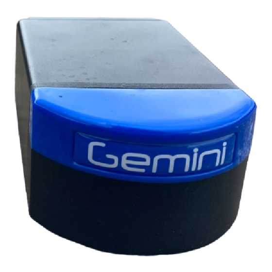
Summary of Contents for Moog Tritech Micron Gemini
- Page 1 Micron Gemini Micron Gemini Product Manual 0729-SOM-00004-01 0729-SOM-00004-01 Page 1 of 46...
- Page 2 Micron Gemini © Tritech International Ltd The copyright in this document is the property of Tritech International Ltd. The document is supplied by Tritech International Ltd on the understanding that it may not be copied, used, or disclosed to others except as authorised in writing by Tritech International Ltd.
-
Page 3: Table Of Contents
Micron Gemini Table of Contents Help & Support ........................4 Warning Symbols ........................5 Introduction ........................... 6 Technical Specifications ...................... 7 Sonar Variants ........................9 Getting started ........................10 Serial System Test Kit ....................... 11 Ethernet System Test Kit ....................12 Assembling the Serial System ................... -
Page 4: Help & Support
Westhill, Aberdeenshire AB32 6JL, UK Telephone +44(0)1224 744 111 Email tritech-support@moog.com Website www.moog.com/tritech Prior to contacting Tritech International Ltd please ensure that the following is available: 1. The Serial Numbers of the product and any Tritech International Ltd equipment connected directly or indirectly to it 2. -
Page 5: Warning Symbols
Micron Gemini Warning Symbols Throughout this manual the following symbols may be used where applicable to denote any particular hazards or areas which should be given special attention: Note This symbol highlights anything which would be of particular interest to the reader or provides extra information outside of the current topic. -
Page 6: Introduction
Micron Gemini Introduction The Micron Gemini takes Tritech’s Gemini Multibeam technology and fits it in a form factor that fits with the Tritech Micron family to create the world’s smallest Multibeam imaging sonar. Having a 90° horizontal field of view and 50m end range, with an update rate up to 20Hz and incredibly compact dimensions the Micron Gemini can be used in applications where size is critical. -
Page 7: Technical Specifications
Micron Gemini Technical Specifications Drawing shown with 750m Micron Gemini fitted with an Impulse MKS(W)-3L10 connector. All dimensions are in mm, not to scale. Acoustic Specifications Operating frequency 720 kHz Angular resolution 2.34° acoustic, 0.7° effective Range 0.2 m to 50 m Number of Beams Horizontal Beam Width 90°... - Page 8 Micron Gemini Interface Supply voltage 12 to 48 VDC Power requirement 5 W-8 W (range dependant) Main port protocol Ethernet (100Base-T) and / or Serial (RS232 or RS485) Auxiliary port protocol Auxiliary port protocol Serial (RS232 or RS485) Main: Impulse Titan™ or Tritech Micron Connector type Aux: Tritech Micron Physical Specifications...
-
Page 9: Sonar Variants
Micron Gemini Sonar Variants The following shows the 3 different connector types, the communication protocols associated with them and depth ratings. Tritech MICRON Connector Depth Rating Communications 300m 750m RS232/RS485 S12683 S12686 Impulse Titan™ Depth Rating Communications 300m 750m Impulse Titan™ MKS(W)-307 Ethernet ONLY S12682... -
Page 10: Getting Started
Micron Gemini Getting started The following instructions are to help the user connect the system together for the first time and be able to successfully power on the unit. In order to prepare the system and test its functionality before mounting to a vehicle, the Micron Gemini requires either an Ethernet or Serial test kit (depending on user requirement). -
Page 11: Serial System Test Kit
Micron Gemini Serial System Test Kit The serial system test kit has different part numbers. This reflects the different mating tails required for the connector fitted to the Micron Gemini purchased. Please reference the serial number of the Micron Gemini and connector variant when in conversation with Tritech. The following serial system tests kits are available: ... -
Page 12: Ethernet System Test Kit
Micron Gemini Ethernet System Test Kit The Ethernet system test kit has different part numbers. This reflects the different mating tails required for the connector fitted to the Micron Gemini purchased. Please reference the serial number of the Micron Gemini and connector variant when in conversation with Tritech. The following serial system tests kits are available: ... -
Page 13: Assembling The Serial System
Micron Gemini Assembling the Serial System Step 1 Connect the breakout assembly to the 10 metre serial test cable, making sure to properly align the Souriau connector and its keyway. Female connector of the breakout assembly A correctly mated Souriau communications and male connector of the test cable cable Step 2... - Page 14 Micron Gemini A USB to serial converter indicating that it is establishing communications Step 5 Once the system has established communication, the LED on the USB connector will be fully illuminated. The system is now ready to operate with the software, green LED’s indicate the transmission and reception of data.
-
Page 15: Assembling The Ethernet System
Micron Gemini Assembling the Ethernet System The assembly of the Ethernet system is similar to the process detailed in the Serial system Step 1 Connect the Breakout assembly to the 10m Ethernet test cable, taking care to properly align the Souriau connector and its keyway. Step 2 The connector on the Gemini and the Power Supply cable should be connected, similar to the instructions given for the Serial System setup (see ”Assembling the... -
Page 16: Installation
Micron Gemini Installation Communications Protocols This section details communication information that should be taken into consideration prior to installation. Serial In order to achieve the maximum performance from the serial link it is recommended that the Tritech USB adapter is used. The Tritech USB allows Genesis and the Gemini to automatically negotiate to the maximum permissible baud rate for the line. -
Page 17: Ethernet
Micron Gemini RS485 This is the preferred serial communications protocol. It is recommended that the minimum speed 921600 baud be used for best overall performance. Autocomms The Tritech USB adapter supports auto negotiation of baud rate and communications protocol. When it starts it always defaults to RS485. If RS232 is required, then you will need to left mouse click on the ID number of the Micron Gemini and select RS232 from the dropdown within the General tab. -
Page 18: Electrical Installation
Micron Gemini Electrical Installation For electrical installation please see the connector pinouts in “Appendix A” For the Micron connector there is a 1 metre test cable available which is terminated to a D- Type Sub-Miniature connector, see “Micron Test Cable - S11640 XXm”. Connector Maintenance Guidelines Mating surfaces should be lubricated with 3M Silicone Spray or equivalent, DO NOT GREASE. -
Page 19: Hardware Installation
Micron Gemini Hardware Installation To correctly mount the Micron Gemini, the blue Gemini logo/mould should be at the top, and the product label at the bottom. BOTTOM The transmit and receive elements are arranged such that they are angled at 0° about the horizontal axis which should be considered when mounting the sonar. - Page 20 Micron Gemini Any metallic clamps should be electrically insulated from the sonar body by either rubber or plastic strips or mounting brackets of at least 3 mm thickness and extending at least 3 mm beyond the clamp boundary to reduce any galvanic corrosion effect. Non-metallic clamps are preferable;...
-
Page 21: Installing The Micron Gemini Using Tritech Mounts
Micron Gemini Installing the Micron Gemini using Tritech Mounts There are multiple ways to affix the Micron Gemini due to its small size and versatility. Tritech have produced Mounting Bracket Kits to enable the customer to adapt to their application, giving users the ability to angle the sonar at either 0° or 10° downward tilt. There is also the Clamp Mounting Bracket which can be used where a quick release system may be more appropriate. - Page 22 Micron Gemini Fixing the Sonar Mounting Bracket to your vehicle at 0° The Sonar Mounting Bracket has both Metric and Imperial mounting hole footprints to allow easy mounting of the adapter. The following instructions assume that holes have been drilled in a mounting plate for your vehicle.
- Page 23 Micron Gemini Step 3 Align the mounting holes that you want to use then fit the mounting bracket as shown onto the 10° adapter. Mounting the Micron Gemini into the Bracket Step 1 Insert the Micron Gemini as shown into the mounting bracket, making sure that the sonar is facing the correct way up.
- Page 24 Micron Gemini Mounting the Micron Gemini into the Clamp Mounting Bracket The clamp mounting bracket allows the user to quickly mount and dismount a Micron Gemini to their vehicle. The clamp mount bracket also allows you to fit the Micron Gemini at a 10° downward tilt. To mount the Micron Gemini onto the clamp follow the instructions below.
- Page 25 Micron Gemini Installing the Micron Gemini onto a Pole Mount System Tritech International Ltd have also created ancillary systems to allow users to Pole Mount a Micron Gemini. This methodology would be perfect for rapid deployment and imaging of an area where ROV access can be limited, or inappropriate.
- Page 26 Micron Gemini Alternative Pole Adapters Items from left to right S11836 Utilises coupling on Ø22mm carbon pole as per USBL system Supplied for US customers for coupling with a MINN KOTA® style Flexible S11904 Composite Shaft S11743 A blank adapter for customer adaption Configured to accommodate "sprung"...
- Page 27 Micron Gemini Fixing the Sonar Mounting Bracket to your Pole Mount Kit Step 1 Secure the Micron Gemini Pole Mount Adaptor to the Gemini DB - Pivot & Pole Mount Assembly using the 2 x M5 x 20 screws and Nyloc nuts. Step 2 Secure the Micron Gemini Pole Mount Adaptor to the Sonar Mounting Bracket,...
-
Page 28: Operation
Micron Gemini Operation Once fully connected to the PC (see “Getting started”) run the Genesis software using the desktop icon: Genesis Software Icon If connecting the Micron Gemini via an Ethernet connection, ensure that the computer IP has been set to the correct range to operate with the sonar. Please see “Setting the computer IP address in Windows®... -
Page 29: Maintenance
Micron Gemini Maintenance General guidance Although the Gemini range is not field serviceable regular care and maintenance of the unit should be carried out. The sonar body and endcap are protected from corrosion by the hard anodised passive surface film. This offers excellent protection in general operating conditions. However, without routine maintenance and in extended immersion in sea water, particularly at raised temperatures and salinity, the chlorides from the salt will start to attack this passive layer. -
Page 30: Sacrificial Anode Information
Micron Gemini Sacrificial Anode Information There is a zinc alloy sacrificial anode fitted to the rear of the Micron Gemini which is intended to prolong its active life when submerged for long periods of time. The lifespan of the anode itself will vary greatly depending on the conditions it is exposed to, so it may need to be changed on a relatively regular basis. -
Page 31: Pressure Sensor Maintenance (300M Only)
Micron Gemini Pressure Sensor Maintenance (300m only) 300m rated Micron Gemini sonars are fitted with a pressure sensor. This sensor requires regular maintenance to inhibit the opportunity for crevice corrosion and salt build up within the pressure sensor port. To maintain the pressure port, first unscrew the seal screw with the S12759 Socket Tool provided (as illustrated). -
Page 32: Troubleshooting
The software reports that no sonars are detected Ensure that the latest revision of Genesis software is running on your computer. Visit www.moog.com/tritech to download the latest version. Check all cabling to the sonar and verify that it is powered correctly with appropriate voltage at the sonar. - Page 33 Micron Gemini Sonar is present but will not ping Ensure that you have OpenGL version 2.1 or greater installed. For Ethernet systems: Check your network settings on the PC. Typing route print into the command line will show the PC routing table. The sonar and PC must be on the same subnet and the PC’s routing table needs to be set up so that packets are routed correctly to the sonar.
- Page 34 Micron Gemini The Micron Gemini will not connect using RS232 on my Multiplexer The issue may lie with the type of connection that you have and the way that the Micron Gemini Autocomms works. See the Autocomms sections for more details. This situation will occur mostly in multiplexer systems that utilise fibre optics, rather than a wired copper connection.
-
Page 35: Appendix A - Connector Details
Micron Gemini Appendix A - Connector Details This appendix covers the pinouts for the various connectors and the associated wiring detail for the Micron Gemini Sonar and its peripherals. Warning Application of reverse supply voltage to the unit or supply voltage across any of the communication connections may lead to equipment damage not covered under the warranty conditions. -
Page 36: Tritech Micron
Micron Gemini Tritech Micron Main Port Cable Core Connector Face View Function Colour RS485 A Yellow RS232 Tx RS485 B Blue RS232 Rx + V DC 0V DC Black RS232 GND Green Shield Cable Sheath Cable colours correct as of 17/03/22 Aux Port Cable Core Connector Face View... - Page 37 Micron Gemini Micron Test Cable - S11640 XXm 0729-SOM-00004-01 Page 37 of 46...
-
Page 38: Impulse Titan
Micron Gemini Impulse Titan™ MKS(W)-307 Bulkhead Face View Function Cable Face View 0V DC +V DC Screen Ethernet Rx + Ethernet Rx - Ethernet Tx + Ethernet Tx - MKS(W)-3L10 The cable view below shows a fully wired Impulse Titan™ 3L10 cable. This covers RS485 and Ethernet combinations. - Page 39 Micron Gemini Note The S11792-KIT2 test kit contains the combined Ethernet and RS485 whip (S11799 Xm/S11800 Xm) and test cable (S11801 Xm/S11802 Xm). These cables cannot support RS232 as there is no RS232 GND core available in the cable. Impulse Titan™ MKS(W)-3L10 Cable Options To clarify the communication options available from the Tritech International Ltd supplied Impulse Titan™...
-
Page 40: Souriau Uts6Jc124S - S09126
Micron Gemini Souriau UTS6JC124S – S09126 Connector Face view Function 0V DC +V DC earth Screen USB to Serial Adapter Cable Options USB to Serial Test Cable - S11942 1m This is designed to replicate a standard PC serial port connection and as such is a DE-9M connector. -
Page 41: Appendix B - Mounting Bracket Details
Micron Gemini Appendix B - Mounting Bracket Details Note Drawings are not to scale. Dimensions in Millimetres (mm) unless otherwise stated. Sonar Mounting Bracket - S11708 Mounting Bracket 10° Adaptor - S11709 0729-SOM-00004-01 Page 41 of 46... -
Page 42: Pole Mount Adapter - S11790
Micron Gemini Pole Mount Adapter - S11790 Clamp Mount Adapter - S11846 Note Only the footprint of the baseplate shown in this dimensional drawing. 0729-SOM-00004-01 Page 42 of 46... -
Page 43: Appendix C - Setting The Computer Ip Address In Windows® Xp
Micron Gemini Appendix C - Setting the computer IP address in Windows® XP The following instructions apply to a computer running Windows® XP, though the sequence for other operating systems will be similar. If the computer is connected to a network already, disconnect it from that network. From the [Start Menu] select [Control Panel]. - Page 44 Micron Gemini Click this item to select it, and then press the [Properties] button. The following dialog should open. Make a note of the settings as currently used by the computer; these will be needed to restore the computer to any existing network. Refer to the appropriate section of this manual for the correct IP address to use.
-
Page 45: Appendix D - Setting The Computer Ip Address In Windows® 7 Or Windows® 10
Micron Gemini Appendix D - Setting the computer IP address in Windows® 7 or Windows® 10 The following instructions apply to a computer running Windows® 7 or Windows® 10, though the sequence for other operating systems will be similar. All screenshots are from a Windows® 7 installation. - Page 46 Micron Gemini This will bring up the [Network and Sharing Center] which allows configuration of any networks on the computer. Click on [Change adapter settings] on the left-hand pane. A list of attached network devices should now present itself. Find the one which the Gemini head is to be connected to and double-click on it.
Need help?
Do you have a question about the Tritech Micron Gemini and is the answer not in the manual?
Questions and answers