
Subscribe to Our Youtube Channel
Related Manuals for Junkers SUPERPURE KBR 120-3


Summary of Contents for Junkers SUPERPURE KBR 120-3
- Page 1 Machine Translated by Google Installation and maintenance guide for professionals Gas condensing boiler SUPERPURE KBR 120-3 KBR 160-3 KBR 200-3 KBR 240-3 KBR 280-3...
-
Page 2: Table Of Contents
Machine Translated by Google Table of Contents Table of Contents 5.5.4 safety valve and automatic 1 Explanation of symbols and safety instructions . 4 1.1 Explanation Fit the vent or safety assembly (on of symbols ..... . 4 1.2 Safety site) . - Page 3 Machine Translated by Google Table of Contents 7.13 Check CO2 setting at full load 11.3 Service displays..... 66 11.4 Error and adjust .
- Page 4 Machine Translated by Google Explanation of symbols and safety instructions 1 Explanation of symbols and safety instructions 1.2 Safety Instructions 1.1 Explanation of symbols Warnings Risk of explosion if you smell gas B Close the gas tap (Æ page 50). Warnings in the text are marked with a B Open windows and doors.
- Page 5 Machine Translated by Google Explanation of symbols and safety instructions Danger from not paying attention to your own safety in emergencies, e.g. B. in case of fire B Never endanger your life. the personal safety always comes first. risk of scalding B Allow the boiler to cool down before inspection and maintenance.
-
Page 6: Product Information
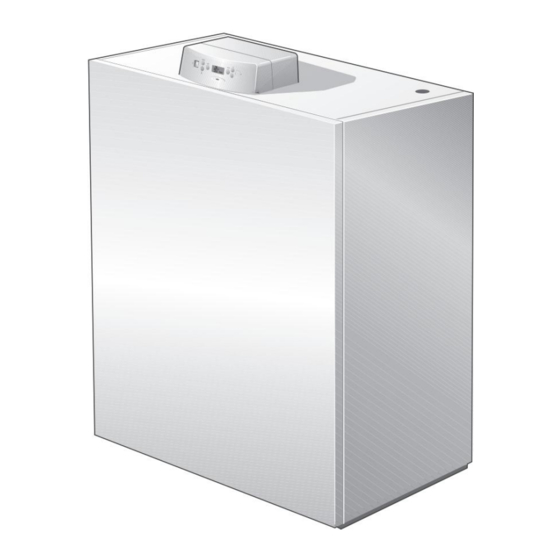
• Spare Parts Catalog Gas condensing boiler • Water quality log • 120 The documents mentioned above are also available via Junkers on the • 160 Internet. • 200 Maximum heating power in kW If you have any suggestions for improving the above documents or if you •... - Page 7 Machine Translated by Google Product details 2.6 Product Overview The boiler is a gas condensing boiler with aluminum nium heat exchanger. Figure 1 Product overview Main circuit board with operating unit gas burner boiler front wall siphon Boiler block with thermal protection burner machine gas fitting boiler casing...
-
Page 8: Connections
Machine Translated by Google Product details 2.7 Dimensions and Connections picture 2 Not included in the delivery connections AKO condensate outlet Connection flue gas GAS gas connection Combustion air line connection (only for room air- independent operation Boiler flow Connection safety valve or safety group boiler return MAG connection diaphragm expansion tank... - Page 9 Machine Translated by Google Product details Boiler size (power in kW) number of members 1124 1124 Width B 1332 1332 Dimension XAA Dimension XRK (= XAL = XGAS) 1008 1008 1216 1216 dimension F 1308 1300 1300 1300 1300 Dimension A Diameter exhaust pipe Ø...
- Page 10 Machine Translated by Google Product details 2.8 Specifications Boiler size (power in kW) number of members Full load kW 120 rated heat output Temperature pairing 50/30 °C part load kW 75.2 87.2 Full load kW 113 rated heat output Temperature pairing 80/60 °C part load kW 56.2 67.6...
-
Page 11: Connection Pressures
Machine Translated by Google Product details Boiler size (power in kW) °C STB protection temperature Permissible operating pressure electrical data IPX0D Degree of protection power connection V/Hz 230/50 Full load W 150 power consumption Part load W 40 Device dimensions and weight mm 851x 1059x 1059x... - Page 12 Machine Translated by Google Product details 2.11 Main circuit board connection diagram Figure 3 Main circuit board connection diagram 1) The total current must not exceed 6.3 A. 6 720 641 801 (2010/11)
-
Page 13: The Boiler
Machine Translated by Google Product details Legend for figure 3: Main circuit board with operating unit main switch Fuse, 6.3 AF (6.3x32mm) Mains supply burner control 230 V/50 Hz component 1 component 2 power input PZB feeder pump PH-HK1 - heating pump 10 WA - heat request (external) 11 FA - outdoor temperature sensor 12 EV - external locking... - Page 14 Machine Translated by Google Product details 2.12 Plant example You can find a representation suitable for installation and other system examples in the planning document. Figure 4 Simplified system example for a mixed heating circuit with hot water outdoor temperature sensor shut-off valve FW200 weather compensated controller heating circuit...
- Page 15 Machine Translated by Google regulations 3 regulations The boiler meets the following requirements in terms of its design and 3.2 Authorization and information requirements operating behavior: •EN677 B Make sure that the installation of a gas condensing boiler is reported to and approved by the responsible gas supply company.
- Page 16 Machine Translated by Google regulations 3.4 Combustion air connection NOTICE: Boiler damage due to corrosion! If the boiler is operated dependent on the room air, the B boiler is not designed as a gravity system installation room must be equipped with the necessary combustion gen or open heating system.
- Page 17 Machine Translated by Google regulations 3.8 Inspection/Maintenance Heating systems require periodic maintenance for the following reasons: • to obtain high efficiency and the to operate the heating system sparingly, • to achieve a high level of operational safety, • to ensure environmentally friendly combustion on a high level to keep level.
- Page 18 Machine Translated by Google transport boilers Transport 4 boilers B Raise the side panels [2] slightly and remove. This chapter describes how to transport the boiler safely. NOTE: Boiler damage from impact kung! The scope of delivery of the boiler contains shock- sensitive components.
- Page 19 Machine Translated by Google transport boilers 4.3 Transport the boiler on rollers Transport the boiler with the help of pipes If the path to the installation site is level, the boiler can also be rolled. To WARNING: Risk of injury from incorrect lifting and do this, use at least 5 pieces of pipe approx.
-
Page 20: Requirements For The Installation Room
Machine Translated by Google installation 5 installation 5.2 Wall clearances This chapter explains how to install the boiler. In detail these are: Install the boiler with the recommended wall clearances. If • Lineup the distances are reduced to the minimum, access to the boiler is •... -
Page 21: Aligning The Boiler
Machine Translated by Google installation 5.3 Aligning the boiler 5.4 Flue gas and air supply connection So that no air can collect in the boiler and 5.4.1 Make the exhaust gas connection the condensate drains unhindered from the condensate pan, the boiler When installing the flue gas connection, note the following: must be leveled. -
Page 22: Connections
Machine Translated by Google installation 5.5 Make hydraulic connections 5.4.2 Make the supply air connection (room air independent gigantic operation) NOTICE: System damage due to leaking connections! The combustion air is fed to the boiler through an external wall connection, through a duct or through a separate line in the duct. B Install the connection lines on the boiler connections without any tension. - Page 23 Machine Translated by Google installation boiler heat Boiler flow (VK) tion Boiler return (RK) 120kW DN 50 bp 2 160 - 280 kW DN 65 PN6 standard flange EN1092 Tab. 12 Dimensions of the water-side connections To avoid contamination on the water side, we recommend installing a dirt trap (accessory) in the return on site.
-
Page 24: Safety Valve And Automatic
Machine Translated by Google installation 5.5.4 Safety valve and automatic air vent 5.5.2 Connect heating return or mount safety group (on site). B Unscrew the counterflange [3] on the RK return. B Attach the counterflange to the return pipe (on site) (Æ Table 12, Page NOTICE: System damage due to incorrect installation! 23). - Page 25 Machine Translated by Google installation B Dismantle the siphon [5]. Neutralization devices are available as accessories B Unscrew the cap [4] and drain the siphon with approx. available that can be integrated into the boiler casing. Fill 2 liters of water. B Mount the siphon.
- Page 26 Machine Translated by Google installation 5.6 Fill the heating system and check for leaks So no leaks during operation B Open the fill and drain cock. occur, check the heating system for leaks before commissioning. Fill the heating system slowly. Observe the pressure display (manometer).
-
Page 27: Connection
Machine Translated by Google installation 5.8 Establish electrical connection B If the heating system has been checked for leaks and there are no leaks, set the correct operating pressure. The boiler is only fully functional when the control unit is installed. When connecting electrical components, also observe the connection 5.7 Establish fuel supply diagram (Æ... - Page 28 Machine Translated by Google installation 5.8.1 Make the mains connection B Lay lines that lead to the rear via the cable duct. A permanent mains connection according to local regulations make fonts. NOTICE: Malfunction due to power failure! B Two screws on the cover of the controller loosen and remove the cover.
-
Page 29: Establishing The Mains Connection
Machine Translated by Google installation B module via the 2-wire BUS on the terminal block 5.8.3 Connecting and installing external heating controllers connect the terminal strip in the controller. B Prepare a sufficiently long 2-wire BUS connection. It is not possible to connect more than one heating controller directly to the boiler at the same time. -
Page 30: Aligning The Boiler Vertically
Machine Translated by Google installation 5.9 Align the boiler vertically So that the side walls and the boiler front wall the boiler must be aligned vertically. B Loosen the nuts [2]. B To turn the boiler vertically using a To align the spirit level [3], turn the screws [1] in or out as required. -
Page 31: Operation
Machine Translated by Google service 6 operation info button The boiler is equipped with the main circuit board and the control panel. Additional operating elements (accessories) can be attached on The info button [4] can be used to open the "Information" menu (Æ site (e.g. -
Page 32: Menu Structure
Machine Translated by Google service 6.2 Menu Structure Settings can be changed as required in the "Settings" menu. The following menus are available for operating the boiler: The "Fault history" menu shows the last 3 latching fault displays. • Status display (Æ Chapter 6.2.1) 6.2.1 Status display •... -
Page 33: Information" Menu
Machine Translated by Google service 6.2.2 "Information" menu B Press the info button to open the information menu. First the word "info" appears for 1 second. If the info button is The following table shows the structure of the "Information" pressed longer, the "Fault history"... - Page 34 Machine Translated by Google service button display meaning Calculated maximum temperature Calculated flow temperature (setpoint) in ºC for heating and chimney sweep operation or frost protection. The flow temperature is always recalculated depending on the heat query. Outside temperature (only visible with weather-compensated control) Outside temperature in ºC 3 dashes indicate a shorted outdoor temperature sensor.
- Page 35 Machine Translated by Google service 6.2.4 "Settings" menu The following table shows the structure of the "Settings" Press the B menu button again to save the value chern. menu. Settings can be changed here as follows: B Press the menu button again to open the menu leaving.
-
Page 36: 35 6.2.5 Chimney Sweep Operation (Service Operation)
Machine Translated by Google service button display meaning 2 fan setting 2.1 Minimum fan modulation Speed adjustment for the lowest degree of modulation. Increase of the lowest degree of modulation on starting load: Input range: - 9 to + 9 Can be changed to - 9 (no transfer). -
Page 37: Commissioning
Machine Translated by Google Installation 7 Commissioning B Set the red pointer [1] of the pressure gauge to the required This chapter describes the commissioning with the basic module of the set an operating pressure of at least 1 bar . controller. - Page 38 Machine Translated by Google Installation 7.2 Note the gas characteristics Only operate the burner with the correct gas Obtain characteristic gas values (Wobbe index and nozzles. calorific value) from the responsible gas supply company (GVU) and note them in the commissioning report (Æ B Responsible gas supply company according to the Chapter 7.21).
- Page 39 Machine Translated by Google Installation 7.4 Check tightness 7.5 Gas type conversion Before initial commissioning, all new gas line sections If it is found that the boiler was ordered for the wrong type must be checked for external leaks. of gas, the gas type must be changed and the type plate updated.
-
Page 40: To 280
Machine Translated by Google Installation 7.5.2 Conversion for the boiler size 160 kW As the 160 kW boiler does not have a gas throttle, the change is made using the high-fire rate adjustment screw. Conversion from gas type H to gas type L: B Unscrew the high-load adjusting screw [1] counterclockwise by half a turn. - Page 41 Machine Translated by Google Installation 7.6 Bleed the gas line B Plug of the gas pressure measuring nipple Loosen the connection flow pressure and ventilation (Æ Fig. 36, 37, 38 [1]) by two turns and attach the hose. B Slowly open the gas tap. B Flare off escaping gas using a water seal.
-
Page 42: 42 7.9 Prepare The Heating System For Operation
Machine Translated by Google Installation 7.8 Check supply air membrane 7.9 Prepare the heating system for operation B Open the main shut-off valve or gas valve. B Check whether the supply air membrane [1] is present on the air intake port [2] and is in contact with the pipe. - Page 43 Machine Translated by Google Installation 7.11 Chimney sweep operation (service B Replacing the gas restrictor at CO2 values below operation) 8.5% (Æ Figure 32, Page 39). The chimney sweep company (service company) is required wobbe index Ø Gas throttle Gas type Ø Gas throttle im for commissioning and maintenance.
- Page 44 Machine Translated by Google Installation 7.14 Check and adjust CO2 setting at Gas valve boiler size 200 to 280 kW partial load B Check the CO2 content. If the value is less than 8.5% or more than 9.4%, correct the B Activate the chimney sweep mode and set the heating load setting using the setting screw V (Æ...
- Page 45 Machine Translated by Google Installation Gas valve boiler size 160 kW Gas valve boiler size 200 to 280 kW B Wait until the burner output has reached 25%. B Wait until 30% burner capacity is reached. B Check the CO2 content. B Check the CO2 content.
- Page 46 Machine Translated by Google Installation 7.16 Functional Tests 7.15 Recording measured values B Carry out the following measurements at a measuring point in the boiler During commissioning and the annual inspection, you must check that connection piece and enter them in the commissioning log (Æ Chapter all regulation, control and safety devices are working properly and, 7.21): where adjustments are possible, that they are correctly set.
- Page 47 Machine Translated by Google Installation 7.17 Measure gas connection flow pressure B Loosen the locking screw of the pressure measuring nipple for the gas connection flow pressure and ventilation (Æ Fig. 49, 50, 51 [1]) by 2 turns. B Attach the measuring hose of the pressure gauge to the pressure measuring nipple [1].
- Page 48 Machine Translated by Google Installation B Front panel with locking screw [3] on top gas type country Connection pressure1) [mbar] Secure the boiler. Min Rated Max. natural gas H (G20) or AT, CH, DE Natural gas L (G25 only DE) Tab.
- Page 49 Machine Translated by Google Installation 7.21 Commissioning report B Confirm and sign the commissioning work that has been carried out and enter the date. commissioning work Measurements page Remarks 1. Fill the heating system and check for leaks Yes: 2. Was the information regarding the water quality in the company book noticed? - Concentration of additives Additives: Concentration:...
- Page 50 Machine Translated by Google Shut down the heating system 8 Shut down the heating system 8.1 Shut down the heating system on the control unit B Automatic air vent at the highest point of the hei Shut down the heating system on the control unit. The burner switches itself off automatically.
- Page 51 Machine Translated by Google Environmental Protection/Disposal 9 Environmental Protection/Disposal Environmental protection is a corporate principle of the Bosch Group. The quality of the products, profitability and environmental protection are goals of equal importance to us. Laws and regulations on environmental protection are strictly observed.
- Page 52 Machine Translated by Google Inspection and Maintenance 10 Inspection and Maintenance Heating systems require periodic maintenance for the following reasons: • to obtain high efficiency and the operate the heating system sparingly (low fuel consumption), • to achieve a high level of operational safety, •...
- Page 53 Machine Translated by Google Inspection and Maintenance 10.3 Internal leak test B Test volume (Vtest) calculated according to the above equation 10.3.1 Determine test volume Gas fitting volume (approximate values) Vtest = Vges. = Vtube + V gas fitting Gas fitting volume up to 50 kW 0.1 liters B Determine the length of the pipeline up to the main fuel shut- off device.
- Page 54 Machine Translated by Google Inspection and Maintenance 10.3.2 Carry out a leak test B Close the main shut-off valve or gas valve. B Loosen the locking screw of the pressure measuring nipple by two turns. B measuring hose of the U-tube pressure gauge to the pressure attach measuring nipple.
- Page 55 Machine Translated by Google Inspection and Maintenance Figure 59 Permissible pressure drop per minute during the internal leak test with gas pressure present Test volume in liters B If no leakage is detected, gas valve Test volume in mbar within one minute exchange.
- Page 56 Machine Translated by Google Inspection and Maintenance 10.4 Check the operating pressure of the heating system B Check the operating pressure of the heating system. NOTICE: System damage due to boiler scale If the pressure gauge pointer falls below the green mark, the formation! operating pressure is too low.
- Page 57 Machine Translated by Google Inspection and Maintenance 10.6 Determine the degree of contamination on the burner and heat exchanger Burners and heat exchangers can be wet cleaned Switch on the heating system at the control unit. be cleaned. B Set the main switch on the control unit to "I". Before you clean the burner and heat exchanger, you must first check and, if necessary, carry out the following points or work steps.
- Page 58 Machine Translated by Google Inspection and Maintenance Call up the "Information" menu Table 14, page 33 ff. shows the structure of the "Information" menu. It contains information about the current settings and the operating status. Settings can only be read here and not changed. B Press the info button to open the information menu.
- Page 59 Machine Translated by Google Inspection and Maintenance B Fastening nuts [3] on the burner shield at the top and unscrew below. B Screws on fan side: Loosen the rear 2 hexagon screws [2] by 2 turns; Unscrew the 2 front hexagon screws [1]. B Carefully pull the burner out to the front.
- Page 60 Machine Translated by Google Inspection and Maintenance Check and adjust electrode position 10.7.3 Clean burner B Burner rods and manifold bars inside out B Measure the distances between electrodes as shown in Fig. 70 and Blow out the outside with compressed air. correct if necessary.
- Page 61 Machine Translated by Google Inspection and Maintenance 10.8 Assemble dismantled parts B All boiler parts subject to inspection or were dismantled for maintenance purposes, reassemble in reverse order. B Check all seals for wear and damage fen. B Replace seals if necessary. B Check the flat gasket in the flange, replace if necessary after completing the inspection and maintenance.
- Page 62 Machine Translated by Google Inspection and Maintenance 10.12 Inspection and Maintenance Records The inspection and maintenance logs also serve as templates for B Sign the inspection work carried out and enter the date. copying. side full load part load full load part load inspection work 1.
- Page 63 Machine Translated by Google Inspection and Maintenance If the inspection reveals a condition that requires maintenance, this work must be carried out as required. part load part load part load part load full load full load full load full load Concentration:________% Concentration:_________% Concentration:________%...
- Page 64 Machine Translated by Google Inspection and Maintenance Date: Page Date: On-demand maintenance ______ ______ 1. Shut down the heating system 2. Clean burner and heat exchanger. 3. Change the seals for the cleaning cover on the heat exchanger 4. Clean the siphon. 5.
- Page 65 Machine Translated by Google Service and fault displays 11 Service and fault displays 11.1 Safety instructions for service work DANGER: Danger to life from explosion of flammable NOTICE: System damage caused by water! gases! Escaping water can damage the electronics B Only carry out work on gas-carrying components with to damage.
- Page 66 Machine Translated by Google Service and fault displays 11.3 Service Indicators The display shows various boiler status indicators in coded form. In the event of a service message, the "Service Symbol" appears on the status display. In the event of a service message, the boiler remains in operation.
- Page 67 Machine Translated by Google Service and fault displays 11.4.2 Identify faults The fault displays are made up of the display code (e.g. E9) and the fault code (e.g. 207). More precise specifications about the type of fault are displayed via the fault code in the "Information" menu (Æ Chapter 6.2.2, page 33 ff.).
- Page 68 Machine Translated by Google Service and fault displays 11.4.3 Faults shown on the display Display rungs kind1) code code description elimination communication with Check the cable connections between the burner control and the Burner machine below control box, replace the burner control if necessary. broken.
- Page 69 Machine Translated by Google Service and fault displays Display rungs kind1) code code description elimination Interruption, return Check the connection line between the burner control unit and the temperature < -5 C. return temperature sensor, replace the line if necessary. Check the electrical connection of the connecting line on the burner control unit and eliminate the contact problem if necessary.
- Page 70 Machine Translated by Google Service and fault displays Display rungs kind1) code code description elimination Temperature difference Press the reset button on the burner control unit. between temperature Check the setting of the non-return valve on the storage tank sensors 1 and 2 too great charging pump and set it to automatic if necessary.
- Page 71 Machine Translated by Google Service and fault displays Display rungs kind1) code code description elimination Interruption, flow Check the connecting cable between the burner control unit and the temperature < -5 °C flow temperature sensor, replace the cable if necessary. Check the electrical connection of the connection line on the burner control unit and eliminate the contact problem if necessary.
- Page 72 Machine Translated by Google Service and fault displays Display rungs kind1) code code description elimination flameout inner New start attempt by the automatic burner. half the stabilization time. No flame inside Check gas connection flow pressure. half the safety time Check gas pressure regulator, inform gas supplier if necessary.
- Page 73 Machine Translated by Google Service and fault displays Display rungs kind1) code code description elimination Internal fault when Check the line to the boiler temperature sensor and replace if necessary. measuring the flow temperature sensor. Check plug connection. Check sensor values according to table, replace if necessary (Æ Fig.
- Page 74 Machine Translated by Google Service and fault displays 11.5 Emergency Operation If communication with the control device is interrupted, the burner control unit automatically switches to emergency mode. In order to maintain the operation of the heating system, the burner control regulates the boiler temperature to 60 °C in emergency mode until communication is restored.
- Page 75 Machine Translated by Google Appendix 12 Appendix 12.1 Voltage values for hot water, boiler, flow and return temperature sensors Resistance temperature tension Resistance temperature tension [°C] [ ÿ] [°C] [ ÿ] 2880 2:12 25313 4.33 2776 2.08 24100 4.30 2677 2.04 22952 4.27...
- Page 76 Machine Translated by Google Appendix 12.2 Sensor characteristics Always measure comparative temperatures (room, flow and flue gas temperature) close to the sensor. The characteristic curves are mean DANGER: Danger to life from electric current. values and have tolerances fraught. Measure resistance at cable ends. B heating system before each measurement current switch off Fig.
- Page 77 Machine Translated by Google Appendix 12.3 Flow resistance on the heating water side Fig. 77 Resistance on the heating water side without non-return valve Flow rate in l/h Pressure loss on the heating water side in mbar Fig. 78 Resistance on the heating water side with non-return valve (cascade) Flow rate in l/h Pressure loss on the heating water side in mbar 6 720 641 801 (2010/11)
- Page 78 Machine Translated by Google Index Index Menu structure................ 32 Measuring point in the exhaust pipe ............. 46 modules Exhaust gas mass flow ..........10 Flue gas (accessories)..............28 temperature..............10 Old device................... 51 Installation room ........
- Page 79 Machine Translated by Google Index Permissible pressure drop..........55 Air supply connection elbow RLU (accessories)......22 Ignition electrode ............... 60 Ignition cables................ 58 6 720 641 801 (2010/11)
- Page 80 Machine Translated by Google Contact us... GERMANY Bosch Thermotechnik GmbH Customer Service Reception Technical advice/ Junkers Germany (24-hour service) spare parts advice Junkersstrasse 20-24 Telephone (0 18 03) 337 330* Telephone (0 18 03) 337 337* Fax D-73249 Wernau (0 18 03) 337 339* www.junkers.com...
Need help?
Do you have a question about the SUPERPURE KBR 120-3 and is the answer not in the manual?
Questions and answers