
Summary of Contents for Chiltrix CXRC1
- Page 1 CXRC1 Radiant Cooling Controller An Add-On Controller Compatible with Most Radiant Heating Controllers Installation & Operation Manual V 1.1 Revised 6-17-2022...
-
Page 2: Table Of Contents
Table of Contents Operation Overview ……………………………………………………………..3 Theory of Operation & Application Notes ………………………..…..4 Installation Overview …………………………..……………………………..5 Fittings & Components Installation ……………………………………….6 Piping & Wiring Diagrams …………………………………………………..9 Sensors Installation……………………………………………………………….10 Sensor Location …………………………………………..……………………..12 Controller Operation …………………………………………………………..13 Condensation Safety & Alarm Output ……………………………...…15 Testing &... -
Page 3: Operation Overview
CXRC1, is required. The CXRC1 is designed to be added to any existing radiant heating controller to enable the additional function of radiant cooling. The existing radiant controller will need to have thermostat(s) that are capable of calling for cooling. -
Page 4: Theory Of Operation & Application Notes
Application Notes: The CXRC1 is not a radiant controller, it is an add-on to most any Brand or model standard radiant controller, to allow you to operate a radiant heating system In a cooling mode without condensation issues. -
Page 5: Installation Overview
Consult with the radiant cooling controller manual to see how to connect any new or additional thermostat or call Chiltrix technical support for assistance. Radiant cooling control can be configured to work with nearly all radiant controllers. -
Page 6: Fittings & Components Installation
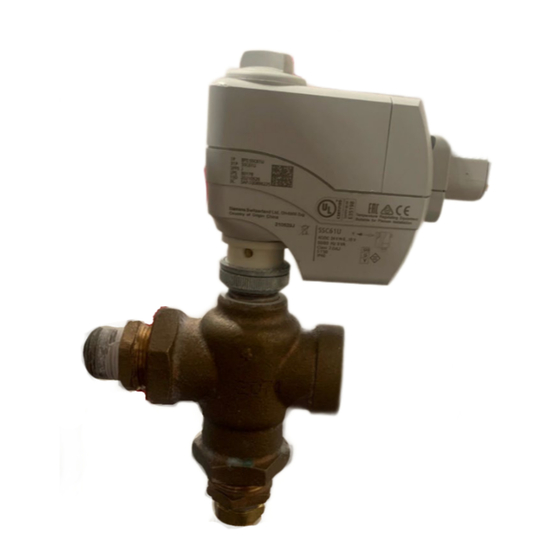
Installation of fittings When installing any fittings, make sure that you use some type of sealant on all threads. Regular Teflon tape will work fine for sealant. The included sensor fitting is 1 ¼ “ FNPT, you can adapt to this as needed for your PEX or copper fittings. - Page 7 A properly installed PT100 sensor assembly Three-way mixing valve...
- Page 8 Installation of Mixing Valve When installing the 3 way valve please use Teflon tape on the fitting ports to prevent any water leakage. The 3 way valve must be installed with the white actuator on top as shown below. Secure the valve to a mounting board if it is directly connected to PEX tubing on all ends.
-
Page 9: Piping & Wiring Diagrams
Example Piping Diagram Wiring Diagram... -
Page 10: Sensors Installation
Mounting of the Controller and Dew Point Sensors Mount the controller in a interior location near the mixing valve and PT100 temperature sensor fitting, and away from any exposure to water or dirt. Mounting tabs are located on the control box on each side. This location may be near the buffer tank, or near the manifolds. - Page 11 Dew Point Sensors CAT6 Sensor Cabling Sensor cabling is an installer-provided item. After determining the sensor locations you will need to measure the length you need and then order or make cable of the correct length with RJ45 connectors in order to connect the sensors to the controller.
-
Page 12: Sensor Location
Dew Point Sensors Proper Location Location, Location, location – where to put the dew point sensors? So here we may hear a lot about classical physics and the ideal gas laws, in particular, Avogadro's Law and Fick’s Laws of Diffusion. Without going deeper into this, these laws tell us that 1) humidity seeks equilibrium and does not need the actual movement of in order to equalized across an area, and 2) that, as counterintuitive as it may seem, a volume of air is lighter... -
Page 13: Controller Operation
CXRC1 Controller Operation The controller has firmware to read the sensors and control the valve position, the end user will need to set a temperature dew point offset. This temperature may the set by the user to automatically track the dew point, or may be set to operate at some delta above or below the dew point. - Page 14 CXRC1 Controller Operation Cont’d In order to change any settings on the controller you will need to hold down the menu button for about 5-10 seconds in order to enter into the main menu. Once in the main menu, you can select “Dew Pt Offset”, this setting is...
-
Page 15: Condensation Safety & Alarm Output
CXRC also disables the circulator pump(s). Alarm Output The CXRC1 has a low-amp (.2a) 5v alarm output that can be used signal an error or loss of communication with dew point sensors. It is recommended that this be connected to a small solid state relay that can be set up to trigger a warning signal such as a bell or other alarm to let you know of any failed sensor. -
Page 16: Testing & Troubleshooting
Problem: I am getting unexpected condensation Solution: Check your calculations for error, or there may be an error in your R-value assumptions. If this cannot be corrected with adjustments on your own, please contact Chiltrix technical support (advanced support dept.). -
Page 17: Determining Set Points / Calculators
(the “radiant surface”. The temperature target offset of the CXRC1 will be based on this surface and therefore the water temperature target can be lower than the dew point. You can use our surface temperature calculator to estimate a safe offset. - Page 18 Find The Best Temperature Offset For Maximum Capacity Please refer to the calculators here: https://www.chiltrix.com/radiant-cooling/radiant-calculators/ Please continue reading for an explanation of how to use the calculators. About these calculators - in spite of the fact that most radiant systems are...
- Page 19 Radiant Cooling (and Heating) Calculators (cont’d) Find The Best Temperature Offset For Maximum Capacity The next input of the Radiant calculator is the temperature. Note this is not the water temperature, rather it refers to the temperature of the radiant surface which we will get to in a moment.
- Page 20 Radiant Cooling (and Heating) Calculators (cont’d) Find The Best Temperature Offset For Maximum Capacity The Surface Temp Tab: This is a handy way to estimate the surface temperature when you know the water temperature, and the R-value of what is between the water (PEX tube) and the radiant surface, and the air temperature of the room.
- Page 21 Radiant Cooling (and Heating) Calculators (cont’d) Find The Best Temperature Offset For Maximum Capacity The Convert K to R Tab: As mentioned, many materials will not have a published R-value that is easy to find. But nearly every material will have a published K value if you look for it.
-
Page 22: Augmentation
Augmentation If you are in a higher humidity climate, you may not be a good candidate for 100% radiant cooling. But even then, radiant cooling can be used along with a properly sized dehumidifier to provide up to 100% of your cooling, or, for augmentation.
Need help?
Do you have a question about the CXRC1 and is the answer not in the manual?
Questions and answers