Table of Contents
Advertisement
Quick Links
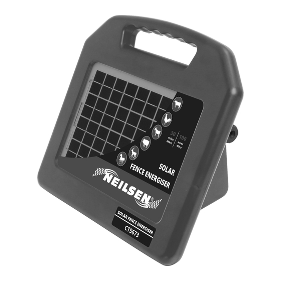
SOLAR FENCE ENERGISER CT5673
INSTRUCTION MANUAL
WARNING: READ ALL INSTRUCTIONS!
If you suspect that the unit is not working, follow these steps:
1. Disconnect the unit from the fence and check that the indicator light is
flashing.
2. Check the battery connection and voltage.
3. Check that the voltage between the live and ground terminals is greater than
7000 v, using a fence voltage tester.
4. If these tests are OK, you have an installation problem.
Cannon Tools Limited
Address:20 Station Road, Rowley Regis, West Midlands, B65 0JU.UNITED KINGDOM
Advertisement
Table of Contents

Summary of Contents for Neilsen CT5673
- Page 1 SOLAR FENCE ENERGISER CT5673 INSTRUCTION MANUAL WARNING: READ ALL INSTRUCTIONS! If you suspect that the unit is not working, follow these steps: 1. Disconnect the unit from the fence and check that the indicator light is flashing. 2. Check the battery connection and voltage.
-
Page 2: Ec Declaration Of Conformity
In case of alteration of the machine, not agreed upon by us, this declaration will lose its validity. Product description: SOLAR FENCE ENERGISER Model: CT5673 Applicable EC Directives: EC Electromagnetic Compatibility 2014/30/EU ROHS - Directive 2011/65/EU and its amendment directives (EU) 2015/863. -
Page 3: Specifications
1. SPECIFICATIONS Excellent fence: 48Km/100Acres Power output : 0.5J @ 500 ohms Delivered power vacuum: 0.63J Solar Consumption: 47mA Voltage Vacuum: 10KV Max Waterproof Rating: IP66Outdoor Use Power Source Battery: DC 12V/8AH Operates Days without Sunlight: up 2 weeks Polysilicon Solar Panel Voltage Output (Vmp): DC18V Polysilicon Solar Panel Current Output (Imp): 0.28A Polysilicon Solar Panel Power Output (Pmax): 5W Solar Panel Size: 303 x 213mm... - Page 4 The adapter and battery cannot be used at the same time,When using battery , adapter cannot be inserted, When using adaptor, need to unplug the battery. DANGER -Do not climb through or under an electric fence. If it is necessary to cross an electric fence use a gate or specially designed crossing point.
- Page 5 shall be incorporated in the electric animal fence at that point or a crossing by means of stiles shall be provided.At any such crossing, the adjacent electrified wires shall carry warning signs. Any part of an electric animal fence that is installed along a public road or pathway shall be identified at frequent intervals by warning signs securely fastened to the fence posts or firmly clamped to the fence wires.
- Page 6 torso. Do not climb over, through or under a multi-wire electric fence.Use a gate or a specially designed crossing point. This unit is not intended for use by persons (including children) with reduced physical, sensory or mental capabilities, or lack of experience and knowledge, unless they have been given supervision or instruction concerning use of the unit by a person responsible for their safety.
-
Page 7: Technical Description
overhead power line, the clearances shall not be less than those shown in Table below. Minimum clearances from power lines for electrical animal fences Power line voltage Clearance ≤ 1000V 3m (10 ft) > 1000V and ≤ 33000V 4m (13 ft) >... -
Page 9: Unpacking And Checking
4. UNPACKING AND CHECKING Carefully remove the product from the packaging and examine it for any sign of damage. If any part is damaged or missing, please contact the seller. Do not attempt to use the product! Note: Battery is in the battery compartment. 5. -
Page 10: Installation
1. Place the unit on a flat surface (handle downwards as shown). Open the battery compartment by unscrewing the screws on the back. 2. Insert a battery (if necessary). 3. Connect the positive (red) lead to the positive (+) terminal on the battery. Connect the negative (black) lead to the negative (-) terminal on the battery (if necessary). -
Page 11: Operation
• with the solar panel facing true south in the northern hemisphere and true north in the southern hemisphere. Mounting the unit The unit may be placed directly onto a flat surface or mounted directly onto a steel Y-post or T-post using the post-mounting slot. Connecting to an electric fence 1. -
Page 12: Battery Information
Model Battery type being charged Battery charger requirements CT5673 12 V 13.8 V, ≤ 1 A When fully charged, the battery should be able to power the unit for up to two weeks with no sunlight. -
Page 13: Maintenance
Warning! Do not use a non-rechargeable battery. Replacement battery details Model Suitable battery type CT5763 12V, 8Ah battery Do not dispose of the battery in a land-fill or in a fire. In the event of a spill or leakage from a sealed lead-acid battery: •... - Page 14 • Keep herds of animals separated • Ration feed Note: Use more wires for smaller animals and wild animals. Polytape should be used when greater visibility is required (e.g. horses). An example of a temporary fence is shown below.
-
Page 15: Troubleshooting
12. TROUBLESHOOTING Problem Action Check that all connections in the fence and ground system are firm and secure. If necessary, clean away any corrosion. Check that the ground rod is pushed firmly into firm ground. The pulse indicator light is Check for faults in the fence-line caused by trees or flashing, but the electric vegetation. - Page 16 13. DISPOSAL At the end of the machine’s working life, or when it can no longer be repaired, ensure that it is disposed of according to national regulations. – Contact your local authority for details of collection schemes in your area. In all circumstances: •...
Need help?
Do you have a question about the CT5673 and is the answer not in the manual?
Questions and answers