Advertisement
Quick Links
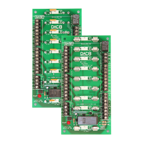
DAC8 / DAC8R
INSTALLATION
Locate the unit inside a UL Listed enclosure, such as a BASE
LVPC Power Cabinet or Econo•Box, close to the source pow-
er supply. Drill or punch (4) 0.187" diameter holes (3/16) to
match the (4) corner holes in the printed circuit board. Push the
nylon standoffs supplied into each hole and snap the module
into place.
POWER SUPPLY WIRING
Common Power Supply for Outputs and Disc Relay Control
Do not cut Common Power Jumpers. Connect 12 or 24VDC
power supply input leads to the
at the lower right side of the module. See Power Input Wiring
Diagram 1.
Separate Power Supplies for Outputs and Disc Relay Control
Cut both Common Power Jumpers. Connect 12 or 24VDC Re-
lay Control power supply input leads to the
input terminals at the lower right side of the module.
Connect 12-24VAC/DC Door Lock power supply input leads
to the
input terminals at the lower right side of
MAIN POWER
the module. See Power Input Wiring Diagram 2.
www.baseelectronics.com
BASE Electronics, Inc. • 2856-C Janitell Road • Colorado Springs, CO 80906 • (719) 540-9697 Fax (719) 540-9698
Direct Access Controller
Features
DAC8
DAC8R
!
Install in accordance with all applicable sections of the National Electrical Code and other State or Local Regulations.
input terminals
MAIN POWER
DIS RLY POWER
Installation and Operations Manual
• Distributes Door Lock Power to 8 Fused or PTC Outputs
• Outputs directly controlled by Access Control System
• Fail-Safe or Fail-Secure selectable per Output
• FACP Interface for Emergency Power Disconnect
• Replaceable Disconnect Relay with Aux Contact
• Small Footprint PCB - 3.0"w x 6.0"h
• Includes Mounting Hardware
Includes (8) 2.0 A replaceable fuses, standard 3AG (¼" x 1 ¼")
Includes (8) 2.5 A PTC auto-resettable fuses
WA R N IN G
Turn off all power feeding the module terminals before servicing or changing input/output
wiring, removing or replacing fuses, etc. Failure to observe this warning may cause electrical shock hazard or
may damage internal or external circuit components.
C
+
-
+
-
+
-
COMMON
POWER
JUMPERS
C
+
-
+
-
+
-
COMMON
POWER
JUMPERS
BASE
Micro-Series
Power Input Wiring Diagram 1
Common Power for
Door Locks and Relay Control
12 or 24VDC
+
12 or 24VDC
-
Use minimum of
18AWG conductors.
leave jumpers intact
Note: Disconnect and Aux Relays are supplied with the
Module and must match Main Power voltage used - specify
voltage when ordering. See Models - Page 4.
Use minimum of
18AWG conductors.
+
12 or 24VDC
-
+
12 - 24VAC or DC
-
Note: Disconnect and Aux Relays are supplied with the
Module and must match Relay Power voltage used - specify
voltage when ordering. See Models - Page 4.
cut both jumpers
Power Input Wiring Diagram 2
Separate Power for
Door Locks and Relay Control
Page 1 of 4
Advertisement

Summary of Contents for BASE Electronics DAC8
- Page 1 See Power Input Wiring Diagram 2. cut both jumpers COMMON POWER JUMPERS Power Input Wiring Diagram 2 Separate Power for www.baseelectronics.com Door Locks and Relay Control BASE Electronics, Inc. • 2856-C Janitell Road • Colorado Springs, CO 80906 • (719) 540-9697 Fax (719) 540-9698...
- Page 2 OUTPUTS above. Output device current rating must be 2.5 Amps or less (for DAC8R) or 2.0 Amps or less (for DAC8). Fail-Safe Control Use normally-closed contacts for controlling Fail-Safe out- When powering devices over considerable distances, the ca- put devices.
- Page 3 Choose the FACP Interface wiring method at right that is ap- with NC Fire Alarm Contact propriate for your installation. If only one DAC8 module is (Interface wiring is fused by first DAC8 Control Power Fuse) being used, then wiring shown to the next module(s) can be ignored.
- Page 4 (4 INCLUDED WITH DAC8 / DAC8R ) The information in this manual is believed to be accurate in all respects. However, BASE Electronics cannot assume respon- sibility for any consequences resulting from the use thereof. The information contained herein is subject to change and BASE Electronics may issue a revision to incorporate such changes at any time.
Need help?
Do you have a question about the DAC8 and is the answer not in the manual?
Questions and answers