
Summary of Contents for EHP TELEBOX PLC
- Page 3 To avoid the risk of electric shock, do not remove the two side covers. There are no user- repairable parts inside the unit. Leave repairs to qualified EHP customer service. There is a risk of contact with non-insulated parts inside the device, which can lead to electric shocks.
- Page 4 The following connections are located on the back of the Telebox SPS: 1. RS-232 interface 2. USB port 3. Power connection The Telebox PLC is configured according to customer specifications before delivery. User- specific changes can be made at any time via the setup of the Telebox PLC...
- Page 5 • Terminal block with strain relief and contact protection • Assembly tool for terminal block Optional accessories for the Telebox SPS: • BNC extension cable for antenna mounting outside the control cabinet • Separate handheld transmitter configured only to the Telebox PLC. • Profibus converter • SD card...
- Page 6 To ensure the functionality of the Telebox PLC, the following requirements apply: -Firm state of the scales: LAH 12.15 or higher (relay drivers are disabled at lower firmware levels) LAH 11.04 or LAH 12.03 (tare & remote function are deactivated with lower firmware...
- Page 7 To do this, open the "Windows Device Manager". Under the tab "Other devices" there is an entry "FT232R USB UART", marked with a yellow "!". Install the driver manually using the supplied "EHP Drivers and Manuals" CD: Right-click the uninstalled device and select...
- Page 8 Select the "Search for drivers on my computer" option. Select the driver - this can be found on the CD supplied. Then click on "Next" to start the installation. Confirm the successful driver installation with the "Close" button. There is now a new device "USB Serial Port" in the Device Manager with a yellow ! in the tab "Other devices".
- Page 9 6. select the tab "Search for drivers on my computer Select the path for the driver, which is located on the supplied CD, then press "Next". Windows will now install the driver. Confirm the successful driver installation with the "Close" button. Table 1 - Manual driver installation The successfully installed Telebox now has an entry in the Device Manager our the "Ports (COM&LPT)"...
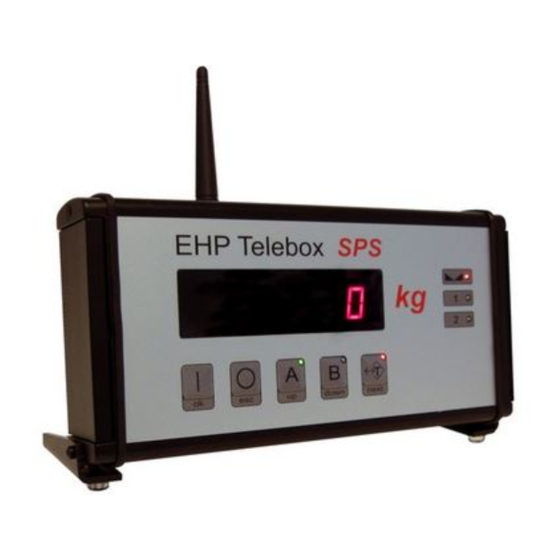
- Page 10 The Telebox PLC starts automatically after the power supply. The Telebox SPS is operated using the five pushbuttons. Figure 3 - Operating keys Telebox PLC Switch on Telebox PLC The display shows the start routine when the power is turned on and then the weight value of the weighing system A is displayed.
- Page 11 Standstill display Balance tared Scales system A active Scales system B active Alternatively, the Telebox PLC can be operated with an EHP IR hand-held transmitter. Key 1 (Tare) Tares the scale Key 2 (Print) Saves the currently displayed value in flash Key 3 (→0)
- Page 12 With the aid of the Telebox PLC, weight values can be recorded, added and stored in a verifiable form. By pressing the "Print" key on the handheld transmitter, the current weight value is stored in the SD flash memory. If, on the other hand, you want to add weight values (e.g. if several units are weighed with the crane scale and the total weight of all weighed units is relevant), use the "Add key"...
- Page 13 Display shows the selected measuring number" Select the next measuring number with UP/Down key. Exit the selected parameter with the ESC key. Pressing the ESC key again terminates the setup. After the reboot, the Telebox PLC is ready for operation again.
- Page 14 After successful data output, the Telebox PLC changes back to the parameter level. P 22" is shown in the display. Exit setup by pressing the ESC key. After the reboot, the Telebox PLC is ready for operation again.
- Page 15 Telebox PLC. Depending on the amount of data, some time may elapse between the return command from the Telebox PLC and the data transfer from the SD card to the RS 232 interface. The successful sending of the measurement data is confirmed by the same command at the...
- Page 16 The measurement data are evaluated with the PC via the SD card. Procedure: Switch off the Telebox PLC. The SD card is located on the right side of the Telebox SPS, protected under a metal cover. You can remove the SD card by tapping on it. Using an SD card reader, the data can be transferred to a PC.
- Page 17 Memory number hundreds digit Memory number tens digit Memory Number One Digit Space Date / Day Date / Day Point / Date Date / Month Date / Month Point / Date Date / Year Date / Year Date / Year Date / Year Space Time / Hour...
- Page 18 • It is not possible to delete the SD card in calibrated systems. The card slot is sealed by a calibration mark to prevent removal of the SD card. • If the maximum capacity of the file 010106.EHP with 99999 records is reached, another file with consecutive number will be generated automatically.
- Page 19 Please note that data is only received here if the scale selected on this channel also has the identical carriage number as is stored in the Telebox PLC (parameters 2 and 13). The control commands for the channel change for High Range radio (500m) and Low Range radio (100m) are different and not compatible.
- Page 20 xx 0C F3 03 Key 11 Shift * xx 0D F2 03 Key 12 Enter * A5 5A C1 00 00 3E 03 Activate transparent mode temporarily A5 5A C2 00 00 3D 03 Disable transparent mode temporarily A5 5A C3 00 00 3C 03 Select scale A A5 5A C4 00 00 3B 03 Select scale B...
- Page 21 External power supply 10-28V Connection instructions Basically, the setpoint outputs of the Telebox PLC must be wired via an additional relay. All commercially available relays with 24V coil voltage can be used. Connect the relays to the ground of the Telebox PLC.
- Page 22 Mounting the connecting cables A mounting tool for the terminal block is included in the scope of delivery. Both rigid and flexible cables can be connected. The use of wire end ferrules is not necessary. Please note that all connection work may only be carried out in a de-energized state. Failure to do so may result in damage to the interfaces.
- Page 23 PLC is made via PIN1 & PIN2 on the series interface. The Telebox PLC is the current indicator and has an integrated reference resistor for determining the reference current. Thus it is possible to operate reference measuring amplifiers with different internal resistances.
- Page 24 Configuration examples: Example 1: A 2t crane scale should be configured from 0 kg to 2000 kg on the 4-20 mA interface. 0 kg corresponds to 4 mA, 1550, 5 kg corresponds to 20 mA. Weight before Weight after Parameter Sign (1.) Value decimal point (2.)
- Page 25 If parameter 14 is set to value 2, the operation of relay port 4 is changed. This becomes High active as soon as the Telebox PLC and the scale are ready for operation and the radio connection has been established. If the radio connection is interrupted for more than 2 seconds, the relay port switches to Low without delay.
- Page 26 This results in the following configuration option: 0 => high active positive weight 1 => high active negative weight 2 => high active positive and negative weight 3 => low active positive weight 4 => low active negative weight 5 => low active positive and negative weight The following applies to the overload relay output 5: 0 =>...
- Page 27 The RS-232 interface may only be connected in a voltage-free state. Non-observance can lead to the destruction of the V24 interface! Either the RS-232 or the RS-485 interface can be used. Simultaneous operation of both interfaces is not possible. Please note the parameterization of parameter 3. The data output of the interface is controlled via parameter 5.
- Page 28 Byte # ASCII Meaning Digit 2 Decimal place of the weight Digit 1 Units digit of the weight specification Scale tare OFF (gross weight) Scale tare ON (net weight) Single range scale in area I in area II No standstill Standstill No key is pressed on the handheld transmitter Key 2 (Print key)
- Page 29 With the extended data protocol (23 bytes) the bytes #23...#27 (tare value) are missing compared to the 28 byte data protocol. Byte 23 is the end of block character (03 Hex). EHP- Standard data protocol Compared to the extended 23 byte data protocol the bytes #18 to #22 (numeric code) are missing.
- Page 30 Byte #: ASCII: Meaning: Start signal no comma (e.g.: 48905) one decimal place (e.g.: 4890,5) two decimal places (e.g.: 489.05) three decimal places (e.g.: 48.905) four decimal places (e.g.: 4.8905) Blank (20H) no sign Plus Minus Digit 5 Most significant digit (left digit) Digit 4 Digit 3 Digit 2...
- Page 31 Byte #: ASCII: Meaning: Scale was switched off manually Scale was switched off by the automatic switch-off function TELEBOX manually switched off Reception disturbance TEST Scale battery charged Prewarn /empty battery of the scale Battery of the scale discharged (1-99) Digit 1 of the scale no.
- Page 32 Optionally you can get an additional converter from EHP Wägetechnik. With this converter you have the possibility to connect the Telebox PLC with a Profibus network. A sample file (GDS file) with the basic configuration of the converter can be found on the supplied Driver &...
- Page 33 If you keep the Up/Down keys pressed for a longer time, the value to be set runs up or down automatically. The values to be set, which can be changed, are signaled by flashing. Explanation of the setup key functions on the handheld transmitter: Key 7 (TEST) OK, confirm selection Key 8 (OFF)
- Page 34 Function Parameter Parameter 1 = On Protocol telebox 0 = Telebox classic 1 = data set scale looped through 4-20 mA Minimum value (4 mA) e.g. 4 mA at 0 kg 4-20 mA Maximum value (20 mA) e.g. 20 mA at 5000 kg P 10 Relay outputs 0= separated 1=parallel (relay output 1) P 11...
- Page 35 Please note which hardware you are using when selecting the frequency. The individual frequencies correspond to the transmitter unit used. Transmitter and receiver must be equipped with the same type of transmitting unit. The different transmitting units are not compatible with each other. Frequency Table High Range Radio IR500 (500m) 433 MHz Band Channel no.
- Page 36 The Telebox SPS USB protocol requires that the scale and channel numbers match. You can only receive data from a scale, provided that both values of the scale are identical with the retrieval commands of the Telebox SPS USB. By pressing the test key of the scale, a routine is shown in the display 88888 = Segment test LAH= Release firmware...
- Page 37 Press the TARA key to activate the parameter. Then use the TEST key to select a desired value between 01 - 28 (corresponds to channel 01 - 28). Confirm and close the parameter by pressing the ZERO key. The display alternately shows P13 and xx, where xx corresponds to the newly set channel number.
- Page 38 To exit the SETUP menu, press the Power On and Power Off keys simultaneously or briefly interrupt the power supply by disconnecting the round plugs on the battery. The time is set via the setup menu. Activate "P00" with the "OK" key. Parameterize the date and time as follows: Page 1: TT-MM (Day-Month) Press the Next key.
- Page 39 With the help of the software, the functions and the radio connection of the Telebox can be tested safely. Copy the "USB Setup Tool" folder from the supplied CD to the computer (assuming unrestricted read and write rights). Then open the program "EHP Setup Tool.exe". Figure 5- EHP Setup Tool...
- Page 40 • "Change unit" Changes the display between kg and t. • "End" ends the application • Help Displays EHP contact information • Language Change language (German/English) Table 3 - Menu tab...
- Page 41 The output format of the software is a CSV file. This is automatically saved under the name EHP.csv in the path stored in the application. The content is saved in follow format: "2021-09-06";"14:42:50";"01";"0.0";"0.0" "YYYY-MM-DD"; "HH:MM:SS"; "WW"; "NNNNN"; "DTTTT" YYYY-MM-DD = date...
- Page 43 Sometimes the malfunction could be caused by another device. Please check any additional devices that may be in use. The Telebox PLC works with error codes. We have listed the error codes that you may be able to correct yourself. If you get an extended system error that is not listed here, please contact the EHP service.
- Page 44 A scale is always stored in the buffer. The display of the scale constantly switches A 2nd EHP scale is in operation occupying the back and forth between 2 different weights. same channel or the mirror frequency of the set channel, switch to another channel.
Need help?
Do you have a question about the TELEBOX PLC and is the answer not in the manual?
Questions and answers