Table of Contents
Advertisement
Quick Links
Advertisement
Table of Contents

Summary of Contents for Ontech GSM 9020
- Page 1 Ontech GSM 9020 User Manual aENGLISHa...
- Page 2 Welcome Thank you for choosing Ontech GSM 9020 We hope that the product will satisfy your needs and that you will find this manual easy to handle and that it guides you in an appropriate way. If you want to learn more, please visit our web site at www.ondico.se, where you can find more information.
-
Page 3: Table Of Contents
Content Overview ..........................5 Content in package ......................6 Get started ..........................6 Necessary programming of the SIM card ......................6 Optional programming of the SIM card ......................7 Position of the contacts on the circuit board ....................9 Installation of internal backup battery ........................ 9 Physical installation ............................... - Page 4 Low battery ..................................25 Internal backup battery .............................. 26 Power failure alarm ..............................26 Delayed power failure alarm ..........................26 Turn off/turn on the unit if an internal backup battery is connected........27 Short range radio – extra relays ..................28 Reference ..........................
-
Page 5: Overview
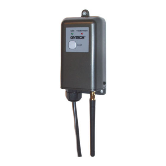
Overview Ontech GSM 9020 is a combined remote relay and an alarm caller and is communicating over the GSM network. The cabinet is in accordance with IP65. The unit is powered by 12 VDC. A 12 V accumulator or the enclosed power adapter can be used. -
Page 6: Content In Package
In the field for telephone number, enter your personal four digit number. This number is the PINCODE you must enter each time you contact your Ontech GSM 9020. Go to ”Optional programming of the SIM card” if you want special functions Turn off the mobile phone and remove the SIM-card. -
Page 7: Optional Programming Of The Sim Card
Optional programming of the SIM card In order to use some of the function you want it can be necessary to program more contacts on the SIM card. See below: NB! To be sure programming is made in a correct way, you can check by requesting an SMS with SIM card settings. - Page 8 in “DEGREE” or write “2” if you want the alarm when the temperature rises above the alarm temperature. Set active temperature sensor (EXTTEMP) (see page 20). 1) If you have an external temp sensor (optional) and you want it to control the temperature alarm and thermostat you have to activate it.;...
-
Page 9: Position Of The Contacts On The Circuit Board
Position of the contacts on the circuit board Fig 1. Upper side of the circuit board. Fig 2. Back side of the circuit board. NB The backup battery is optional and not standard. Installation of internal backup battery If you want to use an internal backup battery (see page 26) you should install this before the physical installation. -
Page 10: Physical Installation
Pull carefully the ”hood” until you can see connector E on the circuit board. Do not pull longer as there is a risk for the flex cable to the membrane switch to disconnect. Remove the protection paper on the tape on the battery Place the battery according to the figure above. -
Page 11: Check The Sim Card Settings
NB. If you shall connect main power, contact a professional electrician. Alarm (page 14). Terminal A. Alarm A is connected to connector “+12” and “A” and alarm B is connected to connector “+12” and “B”. External temperature sensor (page 20). Contact C. Connect the connector. -
Page 12: Testing The Unit
Send an SMS to the unit with a request of the SIM card setting. Write ABCD#8*2# (where ABCD is the PINCODE you have programmed to the SIM card. The unit replies with an SMS with the settings. Testing the unit When you have installed the unit it is recommended to test the function. -
Page 13: Control The Relay With Sms
If the PINCODE is correct the unit replies with a beep. If it is not correct the call is disconnected. Call again and try. Activate the relay by pressing the buttons as follows:: 1*1# The unit confirms with a beep. If there are two beeps, try again. Deactivate the relay by pressing the buttons as follows: 0*1# The unit confirms with a beep. -
Page 14: The Position Of The Relay After A Power Failure
If this is not desired, please set DIP-switch 8 to position ON. Alarm Ontech GSM 9020 can alarm in many different ways. All alarms are sent as SMS to the telephone numbers on the alarm list (see page 7). The unit can be programmed so the relay activates when there is an alarm, see page17. -
Page 15: Wired Alarm
Wired alarm Connect an alarm detector When an alarm detector is activated it will either close or open an electric circuit. It can be a magnetic switch detector, a level detector, a motion detector or any other kind of sensor.. To connect an alarm detector the unit must be opened. -
Page 16: Wireless Alarm Detectors
Detector B Wireless alarm detectors In the 2009 Ondico AB will market wireless alarm detectors. These can be easily connected to work together with Ontech GSM 9020. Up to 7 different detectors can be connected. On Ondico website www.ondico.se will inform more about this! -
Page 17: Delayed Activation Of Alarm Detector
The function is deactivated by removing the contact from the SIM card. Turn off/on the alarm function Each time you start up Ontech GSM 9020 the alarm function is turned on 60 seconds after the green lamp has stopped flashing. This delay is because you shall have time enough to move away from the alarm detectors (compare with an ordinary alarm). -
Page 18: When The Unit Is Alarming
1ab, 3b Indicates all alarms that have been activated since the last acknowledge. The number indicates the units ID number, Ontech 9020 is always no 1, and the others refer to the extra units ore wireless alarm detectors connected. -18-... -
Page 19: Acknowledge An Alarm
(Ontech 9010) connected. An asterisk (*) after the number indicates that the relay is turned on. If Ontech GSM 9020 loose contact with one of the extra relays unit its ID number will not be shown in the SMS. Temp: 24; 24,2 Gives the temperature in degrees C. -
Page 20: Temperature
Temperature Temperature sensors Ontech GSM 9020 will by default use the internal temperature sensor for controlling and alarming. The accuracy is +/- 3 degrees C. The internal temperature sensor is also affected by the relay. If the relay is activated it will indicate 1-2 degrees higher than normal, due to heat produced by the relay.
Need help?
Do you have a question about the GSM 9020 and is the answer not in the manual?
Questions and answers