Table of Contents
Advertisement
Quick Links
MP141E
L-509 Linear Stage
User Manual
Version: 1.6
PI miCos GmbH, Freiburger Strasse 30, 79427 Eschbach, Germany
Phone +49 7634 5057-0, Fax +49 7634 5057-99, Email info@pimicos.com, www.pi.ws
Date: 2022-06-07
This document describes the following linear
stages:
L-509.x0DG10:
with DC gear head motor and rotary encoder
with A/B quadrature signal transmission
L-509.x0SD00:
With 2-phase stepper motor, without encoder
L-509.xASD00:
with 2-phase stepper motor and linear encoder
with sin/cos signal transmission
L-509.x0AD10:
with Active Drive and rotary encoder
with A/B quadrature signal transmission
L-509.x4AD00:
with Active Drive and linear encoder
with A/B quadrature signal transmission
L-509.0x3111:
with DC motor and linear encoder
with sin/cos signal transmission
L-509.0x3132:
with DC motor and rotary encoder
with A/B quadrature signal transmission
L-509.0x3132:
with BLDC motor and rotary encoder
with A/B quadrature signal transmission
Advertisement
Table of Contents

Related Manuals for PI Micos L-509


Summary of Contents for PI Micos L-509
- Page 1 DC motor and rotary encoder with A/B quadrature signal transmission L-509.0x3132: with BLDC motor and rotary encoder with A/B quadrature signal transmission PI miCos GmbH, Freiburger Strasse 30, 79427 Eschbach, Germany Phone +49 7634 5057-0, Fax +49 7634 5057-99, Email info@pimicos.com, www.pi.ws...
- Page 2 The following company names and brands are registered trademarks of Physik Instrumente (PI) GmbH & Co. KG: PI®, PIC®, NanoCube®, PICMA®, PIFOC, PILine®, NEXLINE®, PiezoWalk®, PicoCube®, PiezoMove®, PIMikroMove®, NEXACT®, Picoactuator®, PInano®, NEXSHIFT®, PITOUCH®, PIMag®, PIHera, Q-Motion® © 2020 Physik Instrumente (PI) GmbH & Co. KG, Karlsruhe, Germany. The text, photographs, and drawings in this manual are protected by copyright.
-
Page 3: Table Of Contents
Contents About this Document Objective and Target Group of this User Manual ............1 Symbols and Typographic Conventions..............1 Definition of Terms ..................... 2 Pictures ........................2 Other Applicable Documents ..................3 Safety Intended Use ......................5 General Safety Instructions ..................5 Organizational Measures .................... - Page 4 Installation General Notes on Installation ................... 15 Attaching the L-509 to a Surface ................17 Connecting the L-509 to the Protective Earth Conductor ........20 Affixing the Load to the L-509 .................. 22 Building a Multi-Axis System ..................24 5.5.1 General Notes on Building a Multi-Axis System ..........
- Page 5 10.1.5 Reference Switch Specifications ..............51 10.2 Dimensions ....................... 52 10.2.1 L-509 Positioner ................... 52 10.2.2 Hole Pattern of the Motion Platform of the L-509 ........54 10.2.3 L-500.AV3 Adapter Bracket ................. 55 10.3 Tightening Torque for Screws, ISO 4762 - A2 ............56 10.4 Pin Assignment ......................
-
Page 7: About This Document
1 About this Document About this Document Objective and Target Group of this User Manual This user manual contains the information required for the intended use of the L-509. Basic knowledge of closed-loop systems, motion control concepts, and applicable safety measures is assumed. -
Page 8: Definition Of Terms
Pictures For better understandability, the colors, proportions and degree of detail in illustrations can deviate from the actual circumstances. Photographic illustrations may also differ and must not be seen as guaranteed properties. Version: 1.6 MP141E L-509 Linear Stage... -
Page 9: Other Applicable Documents
C-891 PIMag® Motor Controller MS251E User Manual G-910.RC0102x00 G910M0002EN UserManual G-910.RC0242x00 G910M0001EN UserManual G-910.RC0302200 G910M0003EN UserManual C-885 C885T0002 User Manual C-891.11C885 C891T0005 User Manual C-663.12C885 C663T0004 User Manual C-863.20C885 C863T0005 User Manual PIMikroMove SM148E Software Manual L-509 Linear Stage MP141E Version: 1.6... -
Page 11: Safety
Safety Intended Use The L-509 is a laboratory device as defined by DIN EN 61010. It is intended for indoor use and use in an environment which is free of dirt, oil, and lubricants. In accordance with its design, the L-509 is intended for single-axis positioning, adjusting and shifting of loads at different velocities. - Page 12 Only use the device on the basis of the complete user manual. Missing information due to an incomplete user manual can result in minor injury and damage to equipment. Only install and operate the L-509 after you have read and understood this user manual.
-
Page 13: Product Description
Precision linear stage; 2-phase stepper motor; 100 N load 26 mm capacity; 20 mm/s maximum velocity; ball screw; L-509.2ASD00 52 mm incremental linear encoder, 20 µm sensor signal period, L-509.4ASD00 102 mm sin/cos, 1 V peak-peak L-509 Linear Stage MP141E Version: 1.6... -
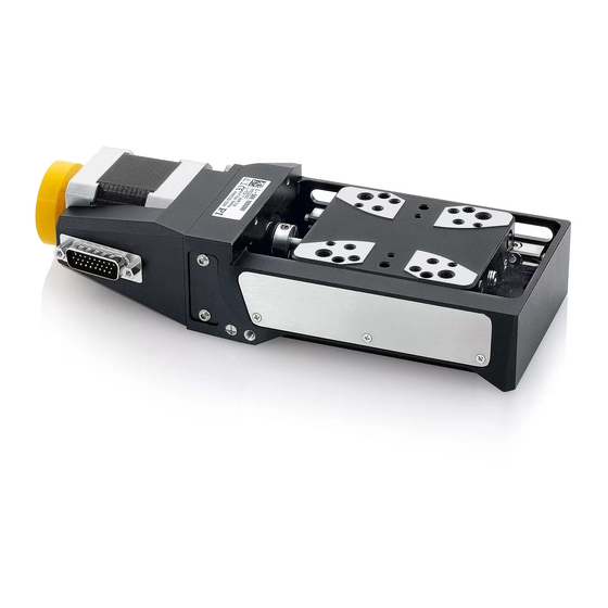
Page 14: Product View
Base body Sensor connector (D-Sub 9 panel plug; L-509.xASD00 and L 509.0x3111 models only) Motor connector (for L-509.x0SD00 / L-509.xASD00 / L-509.x0DG10/ L-509. 0x3111/ L-509. 0x3132/ L-509. 0x5132: HD D-Sub 26 panel plug; for L-509.x0AD10 / L-509.x4AD00: D-Sub panel plug 15) Vibration absorber (L-509.x0SD00 and L-509.xASD00 models only) -
Page 15: Product Labeling
2, 11 WWW.PI.WS Manufacturer's address (website) 2, 12 Old equipment disposal Sensor Linear encoder connector (L-509.x4AD00, L-509.xASD00, L 509.0x3111 models only) 4, 5 Warning sign "Risk of crushing": Reference to dangerous forces (p. 33) L-509 Product series L-509 Linear Stage MP141E Version: 1.6... -
Page 16: Scope Of Delivery
3 Product Description Position Labeling Description Protective earth symbol, marks the protective earth connection of the L-509 (p. 20) Scope of Delivery Item number Component L-509 model. x0AD10 x0DG10 x4AD00 x0SD00 xASD00 0x3111 0x3132 0x5132 L-509.xxxxxx Stage according to the order (p. 7) -
Page 17: Accessories
The L-509.x0SD00 models are not equipped with an encoder. Linear encoder The L-509.xASD00 and L-509.0x3111 models are equipped with an optical linear encoder. For the encoder resolution, refer to the table in the "Specifications" section (p. 45). L-509 Linear Stage MP141E Version: 1.6... -
Page 18: Limit Switches
3.8.4 Integrated PWM Amplifier The L-509.x0AD10 und L-509.x4AD00 models with direct drive are equipped with a PWM amplifier ("ActiveDrive Concept"). The motor and PWM amplifier are installed in a common housing and therefore optimally integrated and shielded. The PWM amplifier only receives the control signals from the controller, whereas the supply voltage is provided via an external power adapter. - Page 19 4 Unpacking Unpacking 1. Unpack the L-509 with care. 2. Compare the contents with the items listed in the contract and the packing list. 3. Inspect the contents for signs of damage. If there is any sign of damage or missing parts, contact PI immediately.
-
Page 21: Installation
Electrostatic hazard Touching the pins in the connections of the L-509 can damage electrostatic sensitive devices (ESD) of the L-509. For this reason, the L-509 is supplied with ESD protection on all connections. Do not remove the ESD protection from the connections until you connect the L-509 to the controller. - Page 22 If necessary, take suitable constructive measures to avoid collisions and instability in the overall system. Avoid or mark danger zones that result from the installation of the positioner and the application, in accordance with the legal regulations. Version: 1.6 MP141E L-509 Linear Stage...
-
Page 23: Attaching The L-509 To A Surface
Only mount the L-509 on surfaces that have the same or similar thermal expansion properties as the L-509. INFORMATION For mounting onto a surface, the L-509 has mounting holes for M4 screws in its base body. The number of holes available depends on the model: L-509.1xxxxx,: 4 mounting holes ... - Page 24 For applications with large temperature changes: The surface should have the same − or similar thermal expansion properties as the L-509 (e.g., surface made of aluminum). You have accounted for the space required to route cables without bending and according to regulations.
- Page 25 3. Insert the screws into all accessible mounting holes and tighten. 4. Repeat steps 2 to 4 for all available concealed mounting holes. 5. Check that the positioner is affixed firmly to the surface. L-509 Linear Stage MP141E Version: 1.6...
-
Page 26: Connecting The L-509 To The Protective Earth Conductor
Connecting the L-509 to the Protective Earth Conductor INFORMATION It is only necessary to connect the L-509 to the protective earth conductor when both of the following conditions are met: The load on the motion platform of the L-509 must be connected to the protective earth ... - Page 27 2. Affix the cable lug of the protective earth conductor using the M4 screw on the protective earth connection of the L-509 as shown in the profile view. 3. Tighten the M4 screw with a torque of 1.2 Nm to 1.5 Nm.
-
Page 28: Affixing The Load To The L-509
5 Installation Affixing the Load to the L-509 NOTICE Impermissibly high load on the stage! An impermissible high load impairs the motion of the platform and can damage the stage. When considering the mass and mounting method of the load, pay attention to the specified maximum permissible forces that may act on the platform (p. - Page 29 2. Use the screws to affix the load on the selected mounting holes in the platform. 3. Check that the load is affixed firmly to the platform of the positioner. L-509 Linear Stage MP141E Version: 1.6...
-
Page 30: Building A Multi-Axis System
5 Installation Building a Multi-Axis System The L-509 can be used in multi-axis systems. Typical combinations: XY system (p. 24) Z system (XZ or XYZ combination) For possible combinations with other positioners, contact our customer service department. (p. 43). - Page 31 Upper stage: Forms the Y axis of the multi-axis system, is attached to the lower stage rotated by 90° Figure 8: Examples of an XY system consisting of two L-509 Requirements You have read and understood the general notes on installation (p. 15).
- Page 32 5 Installation Building an XY system Figure 9: Moving the platform and inserting the screws Lower positioner Upper positioner M4x14 screw Version: 1.6 MP141E L-509 Linear Stage...
-
Page 33: Building A Z System
− Moving the motion platform by hand (p. 41) 2. Affix the upper L-509 to both mounting holes made accessible in the lower L-509: Tighten the screws in the mounting holes completely. 3. Repeat steps 1 and 2 for the two other required mounting holes in the base body of the upper positioner. - Page 34 5 Installation Examples of XZ systems consisting of two L-509 and an adapter bracket Lower positioner Adapter bracket Upper positioner Requirements You have read and understood the general notes on installation (p. 15). You have read and understood the general notes on building a multi-axis system (p. 24).
- Page 35 5 Installation Building a Z system Figure 10: Example of a Z system setup (here with two L-509.2ASD00 positioners) Lower positioner Adapter bracket M6x12 screw Upper positioner M4x14 screw 1. Mount the short side of the adapter bracket onto the motion platform of the lower...
-
Page 36: Connecting The L-509 To A Controller
Connecting the L-509 to a Controller 1. Remove the ESD protection from all connections of the L-509. 2. Connect the L-509 and the controller to each other. 3. Use the integrated screws to secure the connections against accidental disconnection. -
Page 37: Connecting The Power Adapter To The L-509
5 Installation Connecting the Power Adapter to the L-509 Connecting a power adapter is only necessary for the L-509.xxADxx models. Requirements The power cord is not connected to the power socket. Tools and accessories Supplied components: − 24 V wide input range power supply Adapter for the power adapter connection;... -
Page 39: Startup
Only connect the stage to a suitable controller (p. 11). Use the cables that were supplied with your order and your specific positioner/controller combination to connect the positioner to the controller. L-509 Linear Stage MP141E Version: 1.6... - Page 40 Do not place any objects in areas where they can be caught by moving parts. Before connecting the L-509, check whether a macro is defined as the startup macro in the controller, and cancel the selection of the startup macro if necessary.
-
Page 41: Starting And Operating The Positioner
Imprecise approach of the position Settling time is too long If the performance of the L-509 is not satisfactory, check the settings for the servo control parameters of your controller. Starting and Operating the Positioner Requirements You have read and understood the general notes on startup (p. 33). -
Page 42: L-509 Entries In The Pi Positioner Database
6 Startup 6.2.1 L-509 Entries in the PI Positioner Database For PI controllers, you can select the connected stage from a stage database in the corresponding PC software. The appropriate operating parameters are therefore loaded to the controller. You can find a detailed description in the user manual for the controller or in the manual for the PC software used. -
Page 43: Maintenance
Improper maintenance can result in misalignment and failure of the L-509. Only loosen screws according to the instructions in this manual. Performing a Maintenance Run Depending on the operating conditions and the period of use of the L-509, the following maintenance measures are required: Maintenance run The maintenance run serves the purpose of distributing the existing lubricant. -
Page 45: Troubleshooting
Troubleshooting Possible Causes and Remedies Problem Possible causes Solution Mount the L-509 onto an even surface. The Reduced positioning Warped base body recommended flatness of the surface is ≤ 10 µm. accuracy Reduce the load. Make sure that the self-locking... - Page 46 2. Command an axis motion away from the limit switch in the PC software. If the problem that occurred with your system is not listed in the table above or cannot be solved as described, contact our customer service department (p. 43). Version: 1.6 MP141E L-509 Linear Stage...
-
Page 47: Moving The Platform By Hand
It can be necessary to move the platform by hand to provide access to mounting holes for mounting screws in the base body of the positioner. INFORMATION Manual movement of the platform is not possible for the L-509.x0AD10 / L-509.x4AD00 / L-509.x0DG10 models. Figure 11: Position of the vibration absorber... -
Page 49: Customer Service Department
If possible: Take photographs or make videos of your system that can be sent to our customer service department if requested. The latest versions of the user manuals are available on our website (p. 3) for download. L-509 Linear Stage MP141E Version: 1.6... -
Page 51: Technical Data
Drive force in negative di- Typ. rection of motion in X Drive force in positive di- Typ. rection of motion in X Resistance phase-phase Ω Typ. 0.81 0.81 Inductance phase-phase 0.64 0.64 Back EMF, phase-phase, V/kRPM Max. rotational L-509 Linear Stage MP141E Version: 1.6... - Page 52 ± 60 in θY with motion in X) Yaw (Rotational crosstalk µrad Typ. ± 120 ± 60 ± 90 ± 120 ± 60 ± 90 ± 120 ± 60 in θZ with motion in X) Version: 1.6 MP141E L-509 Linear Stage...
- Page 53 Max. Permissible torque in θZ N·m Max. Overall mass 1700 1400 1500 1700 1400 1600 1800 1400 Aluminum, Aluminum, Aluminum, Aluminum, Aluminum, Aluminum, Aluminum, Aluminum, Material steel steel steel steel steel steel steel steel L-509 Linear Stage MP141E Version: 1.6...
- Page 54 Full Motor resolution steps/ rev. Nominal voltage Peak voltage Drive force in negative di- Typ. rection of motion in X Drive force in positive di- Typ. rection of motion in X Version: 1.6 MP141E L-509 Linear Stage...
- Page 55 G-910 G-910 G-910 G-910 G-910 G-910 Operating temperature °C 5 to 40 5 to 40 5 to 40 5 to 40 5 to 40 5 to 40 5 to 40 5 to 40 range L-509 Linear Stage MP141E Version: 1.6...
-
Page 56: Maximum Ratings
L 509.0x3132 L 509.0x5132 48 V 0 Hz 10.1.3 Ambient Conditions and Classifications The following ambient conditions and classifications must be observed for the L-509: Area of application For indoor use only Maximum altitude 2000 m Relative humidity Max. 80 % for temperatures up to 31 °C Linearly decreasing to 50 % at 40 °C... -
Page 57: Limit Switch Specifications
Signal logic Direction sensing by means of different signal levels on the left and right side of the reference switch: The signal level changes from 0 to +5 V when the reference switch is passed. L-509 Linear Stage MP141E Version: 1.6... -
Page 58: Dimensions
For a detailed view (X) der of the motion platform, see "Hole Patterns of the Motion Platform of the L-509" (p. 54). All dimensions in mm. Note that a comma is used in the drawings instead of a decimal point. Figure 12: L-509 versions with stepper motor Version: 1.6 MP141E... - Page 59 10 Technical Data Figure 13: L-509 versions with BLDC, DC, DC gearhead, and ActiveDrive DC motors L-509 Linear Stage MP141E Version: 1.6...
-
Page 60: Hole Pattern Of The Motion Platform Of The L-509
10 Technical Data 10.2.2 Hole Pattern of the Motion Platform of the L-509 Dimensions in mm. Note that the decimal places are separated by a comma in the drawings. Figure 14: Hole pattern of the platform Version: 1.6 MP141E L-509 Linear Stage... -
Page 61: L-500.Av3 Adapter Bracket
10 Technical Data 10.2.3 L-500.AV3 Adapter Bracket Dimensions in mm. Note that the decimal places are separated by a comma in the drawings. Figure 15: L-500.AV3 adapter bracket L-509 Linear Stage MP141E Version: 1.6... -
Page 62: Tightening Torque For Screws, Iso 4762 - A2
Tightening Torque for Screws, ISO 4762 - A2 The following tightening torques for screws according to ISO4762 (corresponds to DIN 912) - A2 may not be exceeded. Value Maximum tightening torque 1.5 Nm 2 Nm 2.5 Nm 3 Nm Version: 1.6 MP141E L-509 Linear Stage... -
Page 63: Pin Assignment
10 Technical Data 10.4 Pin Assignment 10.4.1 HD D-Sub 26 (Male) Figure 17: HD D-Sub 26 panel plug L-509.x0SD00 / L-509.xASD00 models Signal Direction Motor A+ Input Motor A+ Input Motor A- Input Motor A- Input Motor B+ Input Motor B+... - Page 64 10 Technical Data L-509.x0DG10 / L 509.0x3111 / L 509.0x3132 models Signal Direction Motor + Input Motor + Input Motor - Input Motor - Input 5 - 9 Output Limit E1 (neg) Output Limit E2 (pos) Output 13 - 16 -...
-
Page 65: D-Sub 15 (Male)
Encoder B- Output Encoder C+ Output Encoder C- Output Encoder Power (5 V DC) Input 10.4.2 D-Sub 15 (Male) Figure 18: D-Sub 15 panel plug (L-509.x0AD10 and L-509.xAD00 models only) Signal Direction Motor + Input L-509 Linear Stage MP141E Version: 1.6... -
Page 66: D-Sub 9 (Male)
Limit neg. Output Output Encoder A+ Output Encoder B+ Output 10.4.3 D-Sub 9 (Male) Figure 19: D-Sub 9 panel plug (L-509.xASD00 and L-509.0x3111 models only) Signal Direction Linear encoder A+ Output Linear encoder B+ Output Linear encoder C+ Output Linear encoder GND... -
Page 67: M8 4-Pin (Male)
10 Technical Data Signal Direction 10.4.4 M8 4-pin (Male) Connecting a power adapter is only necessary for the L-509.x0AD10 and L-509.x4AD00 models. Figure 20: Power adapter connector M8, 4-pin Signal Direction 24 V DC supply voltage Input 24 V DC supply voltage... -
Page 69: Old Equipment Disposal
PI miCos equipment made available on the market after 13 August, 2005 without charge. Any old PI miCos equipment can be sent free of charge to the following address: PI miCos GmbH Freiburger Strasse 30... - Page 71 12 EU Declaration of Conformity EU Declaration of Conformity An EU Declaration of Conformity has been issued for the L-509 in accordance with the following European directives: EMC Directive RoHS Directive The standards applied for certifying the conformity are listed below.
Need help?
Do you have a question about the L-509 and is the answer not in the manual?
Questions and answers