Table of Contents
Advertisement
Quick Links
Advertisement
Table of Contents

Related Manuals for Magnum Industrial MI-31170


Summary of Contents for Magnum Industrial MI-31170
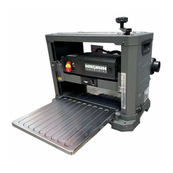
- Page 1 MODEL NO.: MI-31170 OPERATING MANUAL...
-
Page 2: Unpacking & Inventory
UNPACKING & INVENTORY Check shipping carton and machine for damage before unpacking. Carefully remove packaging materials, parts and machine from shipping carton. Always check for and remove protective shipping materials around motors and moving parts. Lay out all parts on a clean work surface. Remove any protective materials and coatings from all of the parts and the planer. - Page 3 ASSEMBLY WARNING! MAKE CERTAIN THAT THE MACHINE IS DISCONNECTED FROM THE POWER SOURCE. ATTACHING DEPTH ADJUSTMENT HANDLE Attach the raise/lower adjustment handle to the shaft located on top of the planer and fasten in place with 1 Hex Socket Head screw. Tighten screw using supplied hex wrench. SEE FIG 1. FIG 1 ATTACHING DUST PORT Facing the rear of the machine, locate the dust port on the cutterhead assembly by turning 2...
- Page 4 ASSEMBLY (cont.) To minimize sawdust accumulation on your work piece, attach either a 2-1/2 in. or a 4 in. vacuum hose to the dust port. The dust port must be snapped shut completely or chips may fly out of the front of the planer. The dust port can be opened to allow chips to flow out the back of the planer when a vacuum system is not used.
- Page 5 ADJUSTMENTS WARNING! MAKE CERTAIN THAT THE MACHINE IS DISCONNECTED FROM THE POWER SOURCE BEFORE ANY ADJUSTMENTS ARE MADE. LEVELING EXTENSION TABLES The extension tables must be level with the planer table. To check the extension tables and adjust if necessary: Lay a straight edge (A) on the planer table (C) with one end of the straight edge over the infeed table (B).
- Page 6 ADJUSTMENTS (cont.) RAISING AND LOWERING HEAD ASSEMBLY The head assembly consists of the cutterhead, knives, feed rollers, cutterhead guard, and the motor. Raising and lowering of the head assembly controls the depth of cut on the planer. To adjust: To raise the head assembly (A), turn the adjusting handle (B) clockwise. SEE FIG 6. To lower the head assembly, turn the adjusting handle counterclockwise.
- Page 7 ADJUSTMENTS (cont.) ADJUSTING / REPLACING KNIVES FOR THE SPIRAL CUTTERHEAD WARNING! MAKE CERTAIN THAT THE MACHINE IS DISCONNECTED FROM THE POWER SOURCE BEFORE ANY ADJUSTMENTS ARE MADE. WARNING! *** Be VERY CAREFUL when handling the knives or cutter tips as they are EXTREMELY SHARP and can cause serious injury!!! *** This 13"...
- Page 8 ADJUSTMENTS (cont.) FIG 7 Note: Proper cleaning of tips and cutterhead is critical to achieving a smooth finish. Dirt or dust trapped between the cutter insert and cutterhead will slightly raise the cutter insert, and make noticeable marks on your work piece the next time you plane. THICKNESS SCALE ADJUSTMENT The thickness scale, located on the right of the planer, shows the thickness of the finished work piece.
-
Page 9: Power Switch
OPERATIONS NOTE: This operations section was designed to give instructions on the basic operations of this planer. However, it is in no way comprehensive of every planer operation. It is strongly recommended that you read books, trade magazines, or get formal training to maximize the potential of your planer while minimizing the risks. - Page 10 OPERATIONS (cont.) REPEAT CUT PRESET The REPEAT CUT preset, located on the right side of the planer, provides a simple way to preset the finished thickness of a work piece. The indicator can be set to various thicknesses. Rotate the indicator to the desired finished thickness.
-
Page 11: Getting Prepared
OPERATIONS (cont.) GETTING PREPARED It is always a good idea to use a piece of scrap wood for your first planing attempt. Also, before each use of the planer, make it a habit of checking for loose fasteners, fittings or hardware. Turn the planer ON and allow it to reach full speed. -
Page 12: Avoiding Snipe
OPERATIONS (cont.) AVOIDING SNIPE Snipe, gouging or depression of the board at the ends, can occur when the board is not properly supported. For work pieces longer than 4 ft, greater care must be taken to reduce the problem because the additional length of the work piece translates into more unsupported weight pulling down on the end of the board. -
Page 13: Brush Replacement
MAINTENANCE (cont.) BRUSH REPLACEMENT Brush life will vary depending on the load placed on the motor. The brushes should be inspected every 10-15 hours of use. To inspect or replace: Remove the brush holders, one of which is shown at (A). The other is located in the same position on the rear of the motor assembly. -
Page 14: Troubleshooting Guide
TROUBLESHOOTING GUIDE Motor and Machine Operation PROBLEM LIIKELY CAUSE SOLUTION Snipe Dull Blades Replace or rotate tips. Readjust (depressions at Infeed or outfeed tables out of tables. Feed scrap of same thickness end of work piece) adjustment. before and after work piece. Residue on rollers. - Page 15 PARTS...
- Page 16 PARTS LIST FOR MI-31170 ITEM NO. DESCRIPTION SIZE Q'ty MI-31170-01 TOP COVER MI-31170-02 HEX SOC HD CAP SCR M6xP1.0x8L MI-31170-03 SHAFT BUSHING MI-31170-04 ELEVATION NUT MI-31170-05 RETAINER BEARING for top cover2 MI-31170-06 UPPER FRAME MI-31170-07 LEFT SIDE PANEL MI-31170-08 RIGHT SIDE PANEL...
- Page 17 PARTS LIST FOR MI-31170 ITEM NO. DESCRIPTION SIZE Q'ty MI-31170-51 CORD CLAMP MI-31170-52 SCR HEX SOC HD LOCK M4XP0.7X10L MI-31170-53 WASHER MI-31170-54 WASHER MI-31170-55 SCREW HEX HD M8XP1.25X20L MI-31170-56 GEAR (INTERMEDIATE) MI-31170-57 RING RETAINING EXT MI-31170-58 GEAR SPINDLE MI-31170-59 RING RETAINING EXT...
- Page 18 PARTS LIST FOR MI-31170 ITEM NO. DESCRIPTION SIZE Q'ty MI-31170-96 SPRING MI-31170-97 PLATE RETAINER MI-31170-98 SCR HEX SOC CAP M5XP0.8X10L MI-31170-99 INFEED ROLLER MI-31170-101 GEAR MI-31170-101A GEAR BOX MI-31170-115 SPACER 15X20X8.5 MI-31170-116 SCR SEMS L/WASH M5XP0.8X12L MI-31170-117 BASE GUIDE RAIL...
Need help?
Do you have a question about the MI-31170 and is the answer not in the manual?
Questions and answers