
Subscribe to Our Youtube Channel
Related Manuals for Salcom 20-90

Summary of Contents for Salcom 20-90
- Page 1 20-90 VHF / UHF Low Power Transceiver with Ethernet PRODUCT MANUAL Version 0.1.1 September 2021 Copyright © 2021 Sea Air and Land Communications Ltd. All rights reserved.
-
Page 2: Warranty And Disclaimer
P a g e Warranty and Disclaimer Salcom products are warranted for a period of 12 months from the date of purchase against faulty materials and workmanship. If any fault should occur, the unit should be returned to the vendor, freight pre-paid. Please include a description of the fault to assist with prompt return. -
Page 3: Table Of Contents
Warranty and Disclaimer ..........................1 Product Overview ............................4 Connectors and Indicators ..........................6 Physical Dimensions ............................7 20-90 Installation and Quick Start Guide ...................... 8 Salcom Message Protocol ........................... 10 Channel Busy Detection ..........................11 CAP codes ..............................12 Input and Output Operation ........................ - Page 4 Glossary ................................42 Accessories and Related Products ......................43 Technical Specifications ..........................44 How to Contact Us ............................46 20-90 VHF & UHF TRANSCIEVER Product Manual Sea Air and Land Communications Ltd, 10 Vanadium Place, Addington, Christchurch 8024, New Zealand September 2021...
-
Page 5: Product Overview
Sacoto configuration tool: The Salcom “Sacoto” configuration software allows full configuration of all functions of the 20-90 transceiver via the serial port or the Ethernet port. Store & Forward repeater: The 20-90 can be configured to operate autonomously as a store &... - Page 6 20-90. ...
-
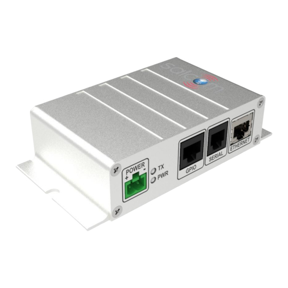
Page 7: Connectors And Indicators
Relay 1 Normally Closed contact Relay 1 Common contact Pin 1 on left side when viewed from front, as above. 20-90 VHF & UHF TRANSCIEVER Product Manual Sea Air and Land Communications Ltd, 10 Vanadium Place, Addington, Christchurch 8024, New Zealand... -
Page 8: Physical Dimensions
P a g e Physical Dimensions The 20-90 has an extruded aluminum case with a mounting flange and screw slots. A dimensioned drawing is provided below. 20-90 VHF & UHF TRANSCIEVER Product Manual Sea Air and Land Communications Ltd, 10 Vanadium Place, Addington, Christchurch 8024, New Zealand... -
Page 9: 20-90 Installation And Quick Start Guide
For transmitting other messages, or monitoring received messages, the RJ12 serial connector, used with the Salcom 12-45 RJ-12 to DB-9 adaptor, provides an RS-232 serial port at 9600 baud, 8N1. Connection may also be made via the Ethernet port, as a TCP or UDP, server or client. - Page 10 Received messages can be filtered by CAP code, and are sent over the serial or Ethernet interface using Salcom Message Protocol. Received messages may be sent to a higher power transmitter, such as the Salcom 20-62, for store and forward operation, or to a Salcom 20-03 I/O expansion unit to provide additional relay and open collector outputs.
-
Page 11: Salcom Message Protocol
P a g e | 10 Salcom Message Protocol Messages are transmitted or received using Salcom Message Protocol (Salcom Protocol) over the serial or Ethernet ports. Salcom protocol takes the basic form: PPXXXXXXX L MMMMMM<CR> Where: PP can be “CA”, “CN”, “ca”, “cn”, “Ca”, or “Cn”... -
Page 12: Channel Busy Detection
| 11 Channel Busy Detection The 20-90 provides a channel busy function to prevent transmission when the channel is in use, or when there is interference on the channel. An output may be configured to provide this busy indication to an external high power transmitter or other channel activity indicator. -
Page 13: Cap Codes
Decode filter The 20-90 provides up to 8 CAP code ranges. It will only decode messages that are within one or more of these ranges (inclusive). The default range is 0000008 to 2000000. The ranges may be in any order, and may overlap. -
Page 14: Input And Output Operation
I/O pin to be used as an input. An external switch may pull the I/O pin to ground, triggering a transmission if the 20-90 is configured to do so. A message may also be transmitted when the switch is opened. -
Page 15: Salcom Relay Control Protocol
If the checksum is enabled, the modulo-10 sum of relay protocol digits, including the checksum digit, must sum to 0 to be considered a valid command. The 20-90 uses four Unit ID’s, starting at the Base ID specified in in the System > Relay Protocol Tab of Sacoto. -
Page 16: 20-90 Output Map
23709 Battery level 23089 Watchdog 23809 Relay protocol example given for a unit base ID of 20. 20-90 VHF & UHF TRANSCIEVER Product Manual Sea Air and Land Communications Ltd, 10 Vanadium Place, Addington, Christchurch 8024, New Zealand September 2021... -
Page 17: Special Functions
CAP code. In the following examples the 20-90 Base ID is configured as 00 (default), thus Base ID + 3 = 03. The response includes the unit ID of the unit sending the response, a letter to identify the function, and the response data. - Page 18 Reset Report RSSI: (Received Signal Strength Indicator) 03709 When a received message triggers the RSSI function, the 20-90 will wait until the channel is clear then transmit an alphanumeric message containing the received signal strength, in dBm, of the message that activated it.
-
Page 19: Pocsag Rapid
0.100 Relay protocol, up to 14 characters. Note: POCSAG rapid is not intended to work with pagers. 20-90 VHF & UHF TRANSCIEVER Product Manual Sea Air and Land Communications Ltd, 10 Vanadium Place, Addington, Christchurch 8024, New Zealand September 2021... -
Page 20: Watchdog Messages
The opening of this output may be used to trigger a transmission by the monitoring 20-90 to provide an alert message when the remote transmitter has stopped working. Two or more 20-90s may monitor each other’s watchdog transmissions. -
Page 21: Store And Forward
It can also act as a range extender for other 20-90 units by placing the 20-90 repeater in a location with better a better path to the receiving site, while still within range of the remote 20-90 transmitters. -
Page 22: Serial Commands
*RPC=24109<CR> Response: OK<CR><LF> Explanation: Close Relay 1 on unit ID 24. Note: The 20-90 unit ID is configured with Sacoto. See “Outputs” for Relay protocol and further information. Query Received Signal Strength Usage: *RSS?<CR> Description: Retrieve signal strength of last message and the current received strength Response: 60,130 <CR><LF>... -
Page 23: Sacoto Configuration Tool
Unzip the downloaded file and run setup_Sacoto_n.n.n.exe Connecting Sacoto to the 20-90 The 20-90 can be connected to a PC via the serial port on the RJ12 connector, or via the Ethernet port. When shipped the 20-90 Ethernet port is configured as a TCP server using an IP address provided by your network’s DHCP server. -
Page 24: Welcome To Sacoto
| 23 Welcome to Sacoto! Icons There are various icons across the top for configuring Sacoto, and for reading and writing 20-90 configuration to or from the unit or a file. Device Menu Reading, writing and setup functions can also be accessed from the “Device” menu. -
Page 25: Sacoto Connection Settings
COM port number. Ethernet Settings When shipped the 20-90 is configured as a TCP server and uses the DHCP server on your network to obtain an IP address. Sacoto provides a discovery tool to find 20-90 units on your network and to discover those unit’s IP address and... -
Page 26: Sacoto Network Discovery Tool
Click on the device you wish to identify. The device data will appear on the right. TCP Server mode: If the IP mode is TCP server, note the 20-90’s IP address, 20-90’s local port. This is all you need to set up the Ethernet connection settings in Sacoto. -
Page 27: Configuring The 20-90 Using Sacoto
Configuring the 20-90 using Sacoto Read the configuration The initial configuration must first be read from the 20-90 or from a file saved on disk. This may then be modified as required and written back to the 20-90. Select “Device->Read device” from the menu, or Click the icon to read the current configuration. - Page 28 If the configuration has been read from a file, or from another 20-90, any differences from the configuration in Sacoto and in the configuration of the 20-90 is unknown. If you want to preserve the settings in the device and only make a few changes you should read from the 20-90 first. Write All If you want to duplicate a known configuration read from another 20-90, or restore a previous configuration saved on disk, then you should select “Device->Write All”...
-
Page 29: Frequency, Power And Busy Settings
Busy Hold: The minimum delay between the channel becoming free and the next transmission. Busy Output: The 20-90 can provide a busy output for an external transmitter. Enable the busy output and select the desired I/O port for the busy signal (active low, overrides all other input and output functions on that I/O port). -
Page 30: Input Triggered Messages
The Input tab is under the IO tab. Here you can configure the input messages, configure POCSAG rapid, and select other input options and parameters. The 20-90 can be configured to transmit messages in response to the state of the inputs. Refer to “Input and output operation”. -
Page 31: Outputs
| 30 Outputs Each output of the 20-90 may be opened or closed by Salcom relay protocol, or by a received CAP code within a range. One output pin may be assigned to be the “Busy” output. See the Inputs and Outputs section and the Salcom Relay Protocol section for a description of the output channels, special functions, and relay protocol. -
Page 32: Cap Code Ranges
CAP Code Ranges The 20-90 provides up to 8 CAP code ranges. It will only decode messages that are within one or more of these ranges. The default range is 0000008 to 2000000. The ranges may be in any order, and may overlap. -
Page 33: Relay Protocol Configuration
See the relay protocol section. The broadcast ID is a second Base ID (96) which may be enabled. If enabled, multiple 20-90 units can be addressed either by their individual ID’s, or as a group using the broadcast ID. -
Page 34: Watchdog Message Configuration
Disabling the watchdog message does not disable the input watchdog messages. The maximum “watchdog repeat time” is 1800 seconds = 30 minutes. 20-90 VHF & UHF TRANSCIEVER Product Manual Sea Air and Land Communications Ltd, 10 Vanadium Place, Addington, Christchurch 8024, New Zealand... -
Page 35: Advanced Features
Serial Pass through When enabled every byte sent to the 20-90 will be transmitted, unaltered, to another 20-90 also configured to serial pass through mode. Serial pass through mode is activated after the unit is reset. -
Page 36: Ethernet Configuration
When shipped, the 20-90 is configured as a TCP server. Other applications can connect to the 20-90’s TCP server. The application should be configured as a TCP client and only requires the IP address and port of the 20-90. Once connected the 20-90 will respond to text messages sent from the application in the same way as a serial connection. - Page 37 IP address and port specified in the “Remote Server” fields. The remote TCP/IP server does not need to know the IP address or port of the 20-90. In TCP/IP client mode the 20-90 will only connect to the specified IP “Remote Server” address and port.
-
Page 38: Salcom Udp/Tcp Test Tool
Monitor received messages. Testing a connection If the 20-90 is configured as a TCP server, the test tool should be a client. Enter the 20-90’s IP address and port number in the “Remote IP Address and Port” fields. -
Page 39: Virtual Serial Port Over Ethernet
Third party software, such as USR-VCOM, can create a virtual COM port on your computer and connect it to the 20-90 over the Ethernet. This allows you to access the 20-90 via the Ethernet in the same way you would access a physical RS-232 port or USB serial port. - Page 40 Select the new port number to assign to the virtual COM port If the 20-90 is a TCP server, you must configure the virtual COM port as a TCP client. Enter the IP address and port number of the 20-90 ...
-
Page 41: Antenna Selection And Installation
Note: The 20-90 is a low power device. Transmission range can exceed 1000m in an open outdoor environment with an outside antenna mounted high above the ground, however buildings, obstructions, radio interference, low gain antennas, and antennas mounted indoors or low to the ground can dramatically reduce range. -
Page 42: Trouble Shooting
Sacoto. Input activated but no transmission Check and write input configuration in Sacoto. Output not activated by received Check message is received on 20-90 serial output message Output disabled Unit ID incorrect or disabled Monoshot timer too short... -
Page 43: Glossary
Typically an independent system would respond to the loss of a watchdog event to provide an alert, activate a failsafe system, or attempt to recover from the fault. 20-90 VHF & UHF TRANSCIEVER Product Manual Sea Air and Land Communications Ltd, 10 Vanadium Place, Addington, Christchurch 8024, New Zealand... -
Page 44: Accessories And Related Products
Accessories and Related Products Name Description Part Number RS-232 serial An RJ-12 to DB9 (RS-232) adaptor and cable for 12-45-0000 Port adaptor connection to the 20-90 serial port Ethernet Standard Ethernet cable. Standard Cable Ethernet Cable Configuration Salcom configuration tool (Sacoto). Can be... -
Page 45: Technical Specifications
P a g e | 44 Technical Specifications Technical Specification 20-90 – VHF / UHF Transceiver Frequency Range 140 - 176MHz - VHF 420 - 480MHz - UHF Frequency Selection User configurable Transmit Power 10mW, 20mW, 50mW, 100mW Transmit Duty Cycle... - Page 46 P a g e | 45 Technical Specification 20-90 – VHF / UHF Transceiver Indicators Power LED (Green) - Slow Flashing = Normal Operation - Fast Flashing = low battery TX/Busy LED (Red) - Flashing fast = Transmitting - Solid on = Chanel busy...
-
Page 47: How To Contact Us
W: www.salcom.com sales@salcom.com Salcom is pleased to confirm that it is a New Zealand FernMark Licensee. The FernMark Licence Programme is the Government’s official ‘country of origin’ accreditation programme, designed to protect and promote New Zealand products to the world. - Page 48 P a g e | 47 20-90 VHF & UHF TRANSCIEVER Product Manual Sea Air and Land Communications Ltd, 10 Vanadium Place, Addington, Christchurch 8024, New Zealand September 2021...
Need help?
Do you have a question about the 20-90 and is the answer not in the manual?
Questions and answers