Table of Contents
Advertisement
Quick Links
I
INTRODUCTION
EMCO's Solid State Voltage Regulating Relay Type EE 301- T is used for regulating the secondary
voltage of power transformer with on-load tap changer . The required dead-band settings are set
by setting the Nominal value and L & R levels independently. The Time Delay setting on the front
panel eliminates the relay operations for momentary fluctuations of the regulated voltage, thus
reducing the number of operations of the tap changer.
When the regulated voltage falls below the specified Under Voltage limit, the control relays are
automatically blocked i.e. there is no voltage correction, and a pair of relay contacts is made
available for alarm.
When the regulated voltage goes above the specified Over Voltage limit, the control relays are
automatically blocked i.e. there is no voltage correction, and the same pair of relay contacts (for
UV) is made available for alarm.
A built-in Tap Position Indicator with 1KW step resistance can be provided optionally to indicate
the Tap No. of the Power Transformer upto a maximum of 35.
The relay uses all solid state circuitry which increases its reliability and life. The output, input
connections are made through a terminal block. However all normal precautions/care in handling/
storage should be observed as for a sensitive electronic instrument.
II
GENERAL DESCRIPTION
EMCO's Solid State Automatic Voltage Regulating Relay Type EE301-T is designed for maximum
operational simplicity. It regulates the secondary voltage of power transformers with on-load
tapchangers. The bandwidth control allows the dead-band to be set in terms of upper (LOWER
VOLTS)and lower (RAISE VOLTS) voltage limits around a particular nominal value with specified
sensitivity.
The Time Delay control allows the regulator to respond only to voltage fluctuations lasting for
periods greater than the selected time delay. Where the voltage correction requires more than one
tap change, the time delay is re-initiated before further tap changes. No special provisions are
required to reset the time delay which resets automatically after the voltage correction. Solid State
Lamps (LEDs) indicate voltage outside the preset limits and control relay operations.
Operation of the RAISE / LOWER Control Relay is automatically inhibited when the voltage falls
below the specified undervoltage limit or goes above the Overvoltage limit. One pair of normally
open relay contacts are provided to effect the tapchanger RAISE and LOWER operations and to
trigger an alarm in case of Undervoltage / Overvoltage conditions. (Only one pair of contacts is
available for either UV or OV)
An alarm in the form of normally open contacts is provided in case of control failure i.e. AVR Relay
continuously showing either 'L' or 'R' command for more than 15 minutes due to malfunctioning of
AVR/OLTC/ any reason.
A built-in Tap Position Indicator with 1KW step resistance can be provided optionally to indicate
the Tap No. of the Power Transformer upto a maximum of 35.
1
Advertisement
Table of Contents

Subscribe to Our Youtube Channel
Summary of Contents for Emco EE301-T
- Page 1 INTRODUCTION EMCO’s Solid State Voltage Regulating Relay Type EE 301- T is used for regulating the secondary voltage of power transformer with on-load tap changer . The required dead-band settings are set by setting the Nominal value and L & R levels independently. The Time Delay setting on the front panel eliminates the relay operations for momentary fluctuations of the regulated voltage, thus reducing the number of operations of the tap changer.
-
Page 2: Specifications
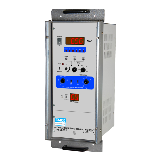
SPECIFICATIONS Auxiliary Supply....110V/230V AC + 15% 50Hz, 15VA PT Supply ......110V AC 50Hz, 1.5VA and readable on display Nominal Value Setting (NVA)..Adjustable between 110V + 10% & readable on display LOWER Volts Setting..... Adjustable between 0.5V to 5V above the NVA and readable on display RAISE Volts setting.... - Page 3 FAMILIARIZATION WITH VARIOUS INDICATIONS / CONTROLS : INDICATIONS 1. 4x7 Segment Display (AVR) Display lights when Auxiliary Supply is 'ON'. 2. 2x7 Segment Display (TPI) Display lights when Auxiliary Supply is 'ON'. 3. ‘L’ Lamp ‘ON’ whenever the PT voltage exceeds the 'LOWER VOLTS’...
- Page 4 5. Time Delay Corrective action takes place only after the Time Delay as set by this control has elapsed and the PT Voltage continues to remain outside the set Lower or Raise limits (but does not fall below the UV / OV limit). 6.
- Page 5 V. OPERATING INSTRUCTION : Check the PT & Auxiliary fuses. Connect 110V / 230V A.C. Aux. Supply to pins 1 & 2 of the Rear Panel Terminal Block. Connect PT Supply to pins 3 & 4 of the Rear Panel Terminal Block. Turn on the instrument by putting Power Switch to 'ON' position.
- Page 6 NOTE : Please note that for the operational safety, RAISE and LOWER relays are interlocked and hence OLTC will never receive two opposite commands simultaneously. 13. UNDER VOLTAGE OPERATION CHECK : Reduce PT Supply below 88V (atleast 87.5V) (UV is factory set at 80% of the Nominal voltage), UV/OV lamp will turn-on immediatelly.
-
Page 7: Test Mode
TEST MODE : When the 'Test / Normal' switch is put in the 'TEST' mode, the PT I/P can be simulated through the 'TEST Control'. However to prevent any undesirable operation of the OLTC, the relays are cut off, but the lamp indications are available. - Page 8 VI. FUNCTlONAL DESCRIPTlON OF VARlOUS MODULES : Mains Transformer : This trasnformer is mounted on a plate towards the Rear Panel . This takes 230V/110V A.C. and steps it down to 16V, 10V & 5V A.C. voltages required for generating dc power. P.T.
- Page 9 VII. FAULT FINDING procedure : Step-1 Check for any physical damage by opening front panels. Step-2 Check the Aux. fuse (300mA) & PT fuse (100mA). If necessary, replace them. (Do not interchange the fuses). Tighten them properly. Step-3 Confirm that the Display PCB's 40 pin connector mate properly with the Main PCB's 40 pin connector Step-4 Connect 'Aux’...
- Page 10 Step-9 Vary the PT I/P to more than 132V (OV level), then the OV indication alongwith ‘L’ indication should come. Decrease the voltage below 127V then OV command goes “off”. However ‘L’ command remains “ON”. Decrease PT I/P voltage slightly less than 112V, ‘L’ will go off.
- Page 11 Table No.1 On Main PCB Test Points Expected Voltage betTP5 &TP7 +12V + 0.5 V betTP6&TP7 -12V + 0.5 V betTP4&TP3 +5V + 0.25V On Display PCB Bet TP4 (on Display PCB ) & TP7 (on Main PCB) (For PT I/P = 110VA.C.) 3.3VAC + 0.2% Bet TP1 (on Display PCB) &...
- Page 12 NATURE OF FAULT PROBABLE CAUSES Unit not switching 'ON' Check fuses, Power Switch, Connections to Rear Panel Terminal Block OK. Check Mains transformer and DC voltages as per Table 1. If faulty replace Main PCB. UV indication permanently 'ON' Check PT supply, PT Fuse and Sense transformer.
-
Page 13: Specification
VIII. OPTIONS LINE DROP COMPENSATOR DESCRIPTION The Line Drop Compensator is optional with the Automatic Voltage Regulating Relay Type EE-301 T. The option is housed in the same enclosure. The Voltage at the generating end and at the receiving end are not the same due to the drop across the line. - Page 14 = the line reactance in ohms/phase. = the line resistance in ohms/phase. The LDC simulates the resistive & reactive drops across the line. The %R setting gives the resistive drop which is in phase with line current. The polarity switch VR selects whether the drop has to be added or subtracted from PT Voltage.
-
Page 15: Very Important
Note down values at which R & L indications come. Let us say they come at 105V& 115V respectively. Pass 1 Amp current through LDC and increase %R setting to 5%. Put polarity switches in + position. Vary the PT Voltage and note value at which R & L indications come. They should be 5.5V above set Values, i.e. - Page 16 4-20mA TPI Output for SCADA. 4-20mA TPI Output option also can be incorporated in the same enclosure. This option provides 4-20mA TPI output on the Rear Panel Terminal Block (pins 20, 21), proportional to Taps 1 to 17, which can be used for SCADA. TESTING PROCEDURE Check TPI, for taps 1 to 17 &...
-
Page 17: List Of Drawings
IX. LIST OF DRAWINGS : Block Diagram 05-ED-09 Front Panel View 05-MD-19 Rear Panel View with Cutout Dimensions & AVR connections 05-MD-20 RECOMMENDED SPARES : Main PCB Display PCB TPI PCB Mains Transformer Sense Transformer... -
Page 19: Time Delay
EMCO AUTOMATIC VOLTAGE REGULATING RELAY TYPE EE 301-T ALL DIMENSIONS ARE IN mm UNLESS STATED OTHERWISE PRODUCT : AVR (301-T) EMCO ELECTRONICS ASSEMBLY: TITLE : FRONT PANEL STICKER (BOTTOM) MATERIAL : SCALE : N.T.S. ISS. DATE APPR. BY DRN. BY DRG. -
Page 21: Warranty
EMCO ELECTRONICS on the component used in equipment. During the warranty period EMCO ELECTRONICS will at its option, either repair or replace the product which prove to be defective provided the product has been used with reasonable care and in accordance with the manuals/product specification. - Page 22 106, Industrial Area, Sion (East), Mumbai-400 022. Tel. : 4096731 / 82 FAULT REPORTING FORM FOR AVR EE301-T Please fill this form when sending the faulty AVR for repairs. This will help us to serve you better. AVR Serial No. :_________________...
- Page 23 Instruction Manual Automatic Voltage Regulating Relay Type EE 301-T EMCO ELECTRONICS Works Unit No. 13, "Kedarnath", Tungareshwar Industrial Complex No. 1, Village sativali, Vasai(E), Dist : Thane - 401208. Tel.:(0250)2481783 / 1804, Fax : (0250)2481087, Email : mumbai@emcoelectronics .org Office 302,Vasan Udyog Bhavan, Sanapati Bapapat marg, OPP.
- Page 24 C O N T E N S Sr. No. TITLE PAGE No. INTRODUCTION GENERAL DESCRIPTION SPECIFICATIONS FAMILIARIZATION WITH INDICATIONS / CONTROLS OPERATION INSTRUCTIONS FUNCTIONAL DESCRIPTION OF VARIOUS MODULES FAULT FINDING PROCEDURE VIII OPTION LIST OF DRAWING & RECOMMENDED SPARES WARRANTY FAULT REPORT FORM...
- Page 25 (ISO 9002 COMPANY) Automatic Voltage Regulating Relay EE 301 - T INSTRUCTION MANUAL...
Need help?
Do you have a question about the EE301-T and is the answer not in the manual?
Questions and answers