
Summary of Contents for Binks GEMS
- Page 1 MAINTENANCE & REPAIR MANUAL GLOBAL ELECTRONIC MIX SOLUTIONS PLURAL COMPONENT MIXING SYSTEM FOR ACID CATALYST 77-2985-R0.5 1/38...
-
Page 2: Table Of Contents
Table of Contents Alarm Guide…………………………………….13.1 Power Outage Cleaning Procedure…….14.1 Trigger Line Connection Reference.14.2 Enclosure Air Plumbing ……………………..15.1 1: System Depressurization Procedure………...4 Connecting Direct Power…………………..16.1 2: Cleaning and Maintenance……...……………..5 Electrical Diagrams………………………….17.1 2.1: Preventive Maintenance…………….6 2.2: Maintenance Schedule……………...7 Pneumatic Diagrams…….………………….17.2 3: Component Names and Locations……..8 3.1: Component Descriptions…...…..….9 4: Control Enclosure ………………………………...10 4.1: Control Enclosure Interior………….11... - Page 3 In this manual, the words WARNING, CAUTION and NOTE are used to emphasize important safety information as follows: NOTE CAUTION WARNING WARNING Read the following warnings before using this equipment STATIC CHARGE READ THE MANUAL READ THE MANUAL Fluid may develop a static charge that must be dissipated through proper grounding read and read and all safety,...
-
Page 4: 1: System Depressurization Procedure
1 : System Depressurization Procedure With air and pressurized working fluids, the GEMS system is constantly under various states of fluid pressure. To perform maintenance and repair or shut down for extended periods the system should be completely depressurized. -
Page 5: 2: Cleaning And Maintenance
2: Cleaning and Maintenance If material leaks occur, be sure to correct the problem and maintain a clean work area. To avoid hardening of paint inside the fluid lines, the system must be cleaned by a complete flushing procedure at the end of operations. -
Page 6: Preventive Maintenance
2.1: Preventive Maintenance The GEMS system requires periodic inspection and regular maintenance for optimum performance and the least possible down time. Follow the corresponding table as a guide to perform routine maintenance at suggested specified intervals. These intervals are recommendations and largely depend on the material being sprayed. -
Page 7: Maintenance Schedule
Disassemble and clean. Clean flow meter Disassemble Clean mix manifold and check valves Disassemble Check fluid hoses for material buildup Disassemble Binks GEMS As Needed Inspection Inspection Description Completed By Date Method Clean and rebuild injector assembly Disassemble Clean and rebuild B pump... -
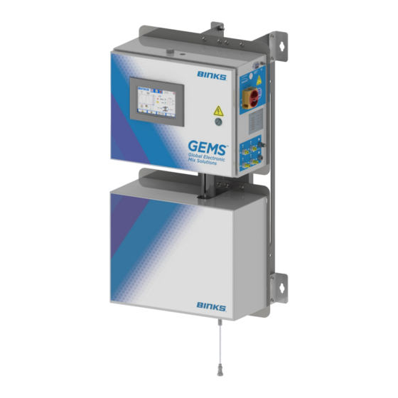
Page 8: 3: Component Names And Locations
This maintenance and repair manual provides part number, troubleshooting, and assembly infor- mation for the Binks GEMS. It is important to understand the names and locations of various compo- nents for use during operation and maintenance. Major components are shown below. -
Page 9: Component Descriptions
3.1: Component Descriptions Color Change Valve, also known as “CCV” — Pneumatic valve used to open and close fluid passages on the dispense pump, mix manifold, and color stack. Mix Manifold— Continuously mixes paint resin (A) and catalyst (B). A built-in check valve on the hardener side prevents back-up of resin into the catalyst pump. -
Page 10: 4: Control Enclosure
4: Control Enclosure ITEMS 3-5 ON BACK OF DOOR ITEM NO. PART NO. DESCRIPTION QTY. 240-3054 ETHERNET BULKHEAD 240-3172 HMI DISPLAY, 7” 240-3173 HMI CABLE 240-3175 ETHERNET CABLE, ANGLED A12464-00 FLASH DRIVE 240-3174 BUZZER 240-3052 AC INLET ASSEM A12411-00 AC LOCKOUT SWITCH 240-3118 AIR CONTROL/ CUT OFF KIT (OPT.) 10/38... -
Page 11: Control Enclosure Interior
4.1: Control Enclosure Interior ITEM NO. PART NUMBER DESCRIPTION QTY. E21-0012 CONTROL BOARD 25766-106 PRESSURE SWITCH 240-3203 24VDC POWER SUPPLY 240-3204 48VDC POWER SUPPLY 240-3202-P STEPPER DRIVE 240-3205 STEP LINEAR ACTUATOR 240-3085-15 SOLENOID MANIFOLD ASSEMBLY 77-2985-R0.5 11/38... -
Page 12: Control Board Detail
4.2: Control Board Detail ITEM NO. PART NO. DESCRIPTION QTY. E21-0012 CONTROL BOARD 21643-411 SCREW 240-3074 TERMINAL BLOCK, 10 POSITION 240-3073 TERMINAL BLOCK, 2 POSITION 240-3077 TERMINAL BLOCK, 4 POSITION 240-3075 TERMINAL BLOCK, 16 POSITION 240-3076 TERMINAL BLOCK, 8 POSITION 12/38 77-2985-R0.5... -
Page 13: Solenoid Manifold Detail
4.3: Solenoid Manifold Detail 240-3085-15 PART NUMBER DESCRIPTION QTY. 240-3087 SOLENOID MANIFOLD BODY 240-3091 SOLENOID VALVE ASSEMBLY 54-4945 1/8” NPT x 1/4” OD TUBE FITTING The solenoid manifold converts 24V electrical signals from the control board into pneumatic air signals for CCV operation. -
Page 14: Assembly Lubricant Note
Reassembly Lubricant Callouts Refer to the icons below to avoid damage and aid assembly of mating parts. Different lubricants are called out depending on the function of the part and lubricant. These triangles are placed next to the corresponding part number label on assembly views. NOTE Follow all assembly procedures and lubricant recommendations to ensure proper operation. -
Page 15: 5: Color Change Valve (Ccv)
5 : Color Change Valve 240-2012-AC The acid-compatible color change valve (CCV) is used throughout the GEMS system. State of the valve may be quickly identified by an indicator on the end cap. If the red indicator is protruding from the surface, the valve is open and fluid flow is permitted. -
Page 16: 6: Color Stack-5 Color
6: Color Stack—5 Color 240-3230-5 Thread Sealant 16/38 77-2985-R0.5... -
Page 17: Color Stack Parts List
6.1: Color Stack Parts List PART ITEM NO. DESCRIPTION QTY. NUMBER 20-2848 ELBOW, 1/4 NPT SS 20-6955 ELBOW, 5/32” ODT LSFI0033-00 3/8” JIC X OD TUBE CONNECTOR 240-2012-AC ACID COMPATIBLE COLOR VALVE 23165-430 O-RING 77578-16C 1/4-20 x 1/2” BHCS CCV-16-SS CENTER MANIFOLD BLOCK CCV-17-SS INLET MANIFOLD BLOCK... -
Page 18: 7: Mix Manifold
7: Mix Manifold 240-3240 Gun Lubricant Thread Sealant ITEM NO. PART NUMBER DESCRIPTION QTY. 20-6955 ELBOW FITTING 107-1449 DM NIPPLE, 1/8” NPT x #4 JIC 240-2012-AC HIGH PRESSURE COLOR VALVE 240-3047-1 INJECTOR ASSEMBLY 240-3049-1 MANIFOLD ASSEMBLY 240-3155 1/4-20 HEX STANDOFFS 240-3236 ADAPTER, 1/4 NPT x #4 JIC 77578-56C... -
Page 19: Mix Manifold Maintenance
7.1: Mix Manifold Maintenance and Repair Reduced flow through the mix manifold indicates dried or hardened paint buildup. Paint or solvent backing into the hardener tube indicates a leak or malfunction of the injector assembly (see below). These items may require disassembly and cleaning to restore mixing and flow performance. -
Page 20: 8: Fluid Panel Components
8: Fluid Panel Components ITEM PART NUMBER DESCRIPTION QTY. 240-3276 FLOW METER 240-3114-A-6 FLOW METER CABLE (STANDARD 6 FT) 240-3213 ACCESSORY SOLVENT METER — 240-3241 RESIN HOSE 240-3231 STATIC MIX ASSEMBLY 240-3242 CATALYST HOSE 20/38 77-2985-R0.5... -
Page 21: 9: Flow Meter Guide
9: Flow Meter Guide 240-3276 ASSEMBLY: LUBRICATE THREADS AND TAPERED SURFACES WITH PETROLEUM GREASE AND TORQUE ITEMS 1 & 3 TO 50 FT-LBS PART # DESCRIPTION 76628-00 TUBE ADAPTER A12712-01 FLOW METER 240-3237 JIC ADAPTER 9.1: Disassembly and Servicing 1. Disconnect sensor cable (2, opposite page) from the flowmeter sensor. Remove meter for service to a suitable clean area to perform maintenance. -
Page 22: 10: Dispense Pump
22/38 77-2985-R0.5... - Page 23 10: Catalyst Pump The catalyst pump meters catalyst to the mix manifold. Using flow rate input from the gear flow meter, the system controller directs the pump’s stepper motor to precisely dispense catalyst at the required ratio. With very low-speed capability and true positive displacement, the catalyst pump can accurately provide ratios from 1:1 to 100:1, depending on flow rate.
-
Page 24: Drive Assembly
10.1: Drive Assembly Note: Lubricate the shaft of item 3 using Dupont Krytox GPL 206 as needed Note: Loctite 242 must be applied when reinstalling items 4 and 14 24/38 77-2985-R0.5... - Page 25 10.1: Drive Assembly ITEM PART NUMBER DESCRIPTION QTY. 240-3060 LINEAR POTENTIOMETER ASSEMBLY 240-3065 POTENTIOMETER WIPER ASSEMBLY 240-3205 STEPPER MOTOR WITH LEAD SCREW 20-2195 1/4-20 x 3/4” SHCS 76566-32C 1/4-20 x 1” SHCS 240-3048 MOTOR MOUNT ASSEMBLY 20-6952 O-RING SS-6505-CD 1/4-20 FLAT WASHER SS-1505-CD 1/4-20 LOCK WASHER SS-655-ZN...
-
Page 26: Fluid Assembly
10.2: Fluid Assembly 240-3208 Gun Lubricant Torque to 10ftlbs (14Nm) Use anti-seize Thread Sealant 26/38 77-2985-R0.5... - Page 27 10.4: Fluid Pump Parts List ITEM NO. PART NUMBER DESCRIPTION QTY. 20-6942 SEAL HOLDER O-RING 20-6943 CYLINDER O-RING 20-6953 JAM NUT 20-6955 ELBOW, 5/32” TUBING 107-1439 DM NIPPLE ADAPTER 237-727 FLAT WASHER 237-729 RETAINING RING 240-2012-AC COLOR VALVE 240-3016-1 BOTTOM BLOCK 240-3018-200 CYLINDER, 200CC 240-3029...
- Page 28 10.6: Rod Seal Replacement Procedure If hardener becomes visible in the oil reservoirs the rod seals should be replaced. First ensure that the system is powered off and disconnected from the electrical power source. Completely de-pressurize the system by following the System Depressurization Procedure in 77-2984 Operations Guide.
- Page 29 10.7: Linear Potentiometer Replacement The linear potentiometer is a permanent part of the linear pot bracket assembly. If the linear potentiometer becomes worn or damaged, the pot/bracket assembly should be replaced. 1. Be sure that the system is fully depressurized before working on it by following the 3.2: System Depressurization Procedure as described in 77-2984 Operations Guide.
-
Page 30: Dispense Pump Removal
10.8: Setting Dispense Pump Limits If the linear pot bracket is replaced, the system will require reset of upper and lower limits to ensure proper functionality. Note that this screen should not be used except in rare cases. Shut the machine off when replacing the linear pot bracket as described in 10.7: Linear Potentiometer Replacement. -
Page 31: Electrical Diagrams
17.1: Electrical Diagrams 77-2985-R0.5 31/38... - Page 32 32/38 77-2985-R0.5...
- Page 33 77-2985-R0.5 33/38...
- Page 34 34/38 77-2985-R0.5...
- Page 35 77-2985-R0.5 35/38...
-
Page 36: Pneumatic Diagrams
17.2: Pneumatic Diagrams 36/38 77-2985-R0.5... - Page 37 As Viewed from Back Side of Enclosure: ACO/GIB2 TRG2 TRG1 GIB1 77-2985-R0.5 37/38...
- Page 38 WARRANTY POLICY Binks products are covered by Finishing Brands one year materials and workmanship limited warranty. The use of any parts or accessories, from a source other than Finishing Brands, will void all warranties. For spe- cific warranty information please contact the closest Finishing Brands location listed below.