Table of Contents
Advertisement
Installation Manual and Operating Instructions
Gas Heaters
miniMAXX
WR 11 -2 .B..
WR 14 -2 .B..
WR 18 -2 .B..
Read installation manual prior to installation of this unit!
Read user manual before putting this unit in operation!
Observe the warnings in the manuals!
The installation room must fulfill the ventilation requirements!
Installation by an authorised person only!
Advertisement
Table of Contents

Related Manuals for Junkers miniMAXX WR 11-2 B Series

Summary of Contents for Junkers miniMAXX WR 11-2 B Series
- Page 1 Installation Manual and Operating Instructions Gas Heaters miniMAXX WR 11 -2 .B.. WR 14 -2 .B.. WR 18 -2 .B.. Read installation manual prior to installation of this unit! Read user manual before putting this unit in operation! Observe the warnings in the manuals! The installation room must fulfill the ventilation requirements! Installation by an authorised person only!
-
Page 2: Table Of Contents
Table of contents Table of contents Warnings and symbols Safety Instructions Key to symbols Information about the heater Category, type and approval no. Technical identification code Package contents Description of the heater Special accessories Dimensions Functional diagram of the heater Electrical diagram Function 2.10... -
Page 3: Warnings And Symbols
Warnings and symbols Warnings and symbols Safety Instructions Client information B Inform the client about the function and operation of If there is a smell of gas: the appliance. B Close the gas valve. B This appliance is not intended for use by persons B Open windows. -
Page 4: Information About The Heater
Information about the heater Information about the heater Category, type and approval no. • Combustion chamber without tin/lead covering • Water valve in fibreglass-reinforced polyamide, 100% recyclable 0464 • Automatic adjustment of the water flow by means of Model WR 11/14/18 -2 B... a device which permits a constant flow to be main- tained in spite of variable pressure supplies Category... -
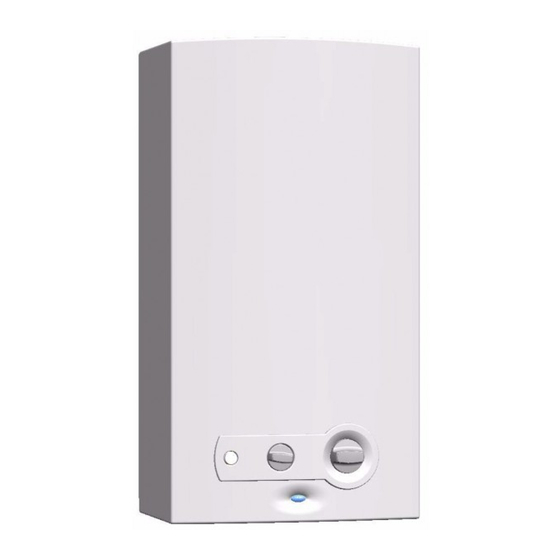
Page 5: Dimensions
Information about the heater Dimensions Fig. 1 Combustion chamber LED - Burner status check Burner Switch / LED - Battery status check Temperature/volume selector Front Gas connection Opening for mounting on the wall Ignition unit Connection collar to the combustion gases pipe Battery compartment Flue with non-return device Power selector... -
Page 6: Functional Diagram Of The Heater
Information about the heater Functional diagram of the heater Fig. 2 Functional diagram Pilot burner Diaphragm Spark plug Main gas valve Ionisation probe Maximum gas adjusting screw Combustion chamber Gas supply pipe Main burner Gas filter Injector Hot water pipe Screw for measurement of pressure in burner Ignition unit Screw for measurement of input pressure... -
Page 7: Electrical Diagram
Information about the heater Electrical diagram Fig. 3 Electrical diagram Spark plug Pilot valve (normally closed) Ionisation probe Temperature limiter Micro-switch Flue gas safety device Ignition unit Diaphragm valve Battery compartment LED - Burner status check Servo valve (normally open) Switch / LED - Battery status check Function This gas heater is equipped with automatic electronic... -
Page 8: 2.10 Technical Characteristics
Information about the heater 2.10 Technical characteristics Technical characteristics Symbol Units WR11 WR14 WR18 Power and flow Nominal useful power 19,2 23,6 30,5 Minimum useful power Pmin Useful power (adjustment range) 7 - 19,2 7 - 23,6 7 - 30,5 Nominal thermal flow 21,8 34,5... -
Page 9: Regulations
Regulations Regulations Any local by-laws and regulations pertaining to installa- tion and use of gas-heated appliances must be observed. Please refer to the laws that should be attended in your country. ? ??? ??? ??? (YYYY/MM) -
Page 10: Installation
Installation Installation • Respect the minimum installation clearances indi- Danger: Explosion cated in Fig. 4. B Always turn off the gas cock before car- • The heater must not be installed in locations where rying out any work on components the room temperature can reach 0 °C which carry gas. -
Page 11: Heater Mounting
Installation • The extremity of the evacuation pipe must be pro- B Identify the cold water pipe (Fig. 5, item A) and the tected against wind/rain hot water pipe (Fig. 5, item B), so as to avoid any pos- sible mis-connection. Caution: B Connect the water pipes to the water valve using the provided connection accessories. -
Page 12: Operating Instructions
Operating instructions Operating instructions Before starting up the heater Open all water and gas blocking devices. Purge the pipes. Caution: B Initial startup must be performed by a qualified technician who will provide Caution: the client with all the necessary infor- The front panel in the burner and pilot mation for optimum operation of the burner area may reach high temperatures,... -
Page 13: Temperature/Flow Adjustment
Operating instructions Remove threaded bushing (pos. 2) from water valve. Empty the appliance of all water. Fig. 10 Higher water temperature. More power. Fig. 13 Purging Retaining clip Threaded bushing Fig. 11 Temperature/flow adjustment B Turn anti-clockwise Increases flow and decreases water temperature. Fig. -
Page 14: Adjustments
Adjustments Adjustments Factory settings B Turn on the heater with the power selector set to the left (maximum position). Sealed elements must not be opened. Natural gas Heaters for natural gas H (G 20) are supplied sealed from the factory after being adjusted to the values indi- cated on the rating plate. -
Page 15: Maintenance
Pilot and main burner basis (inspection) or if necessary (maintenance). These jobs can only be done by a Junkers Technical B Remove and clean pilot burner. Assistance delegate. B Remove and clean pilot injector. - Page 16 Maintenance Function check* Flue gas safety device function check: B Disconnect flue pipe; B Replace with pipe (about 50 cm long) with sealed end; B Fit pipe vertically; B Start up appliance at rated output and set tempera- ture control to maximum temperature; Under those conditions, the appliance should shut down after two minutes.
-
Page 17: Problems
Problems Problems Problem/cause/solution Assembly, maintenance and repairs must be performed by qualified technicians only. The following chart offers solu- tions to possible problems (solutions followed by an * must be undertaken by qualified technicians only). Problem Cause Solution The heater does not ignite. Batteries flat or not inserted cor- Check position and replace them. -
Page 18: Environmental Protection
Environmental protection Environmental protection Environmental protection is a basic company strategy of Junkers. The quality of our products, profitability and environmental protection are equal-ranking goals for us. Laws and regulations concerning environmental protec- tion are strictly observed. We use the best possible tech-... - Page 19 ? ??? ??? ??? (YYYY/MM)
Need help?
Do you have a question about the miniMAXX WR 11-2 B Series and is the answer not in the manual?
Questions and answers