Table of Contents
Advertisement
Quick Links
Advertisement
Table of Contents

Related Manuals for TEKTRO CHEETAH


Summary of Contents for TEKTRO CHEETAH
- Page 1 CHEETAH O w n e r ' s M a n u a l...
- Page 2 About Manual This manual contains details of the product, information on its operation and maintenance, and other helpful tips for owners. Read it carefully and familiarize yourself with the E-Bikes before using it to ensure safe use, reduce risk of damage and premature wear, and prevent accidents. Be sure to retain this manual as your convenient E-Bikes information source.
-
Page 3: Table Of Contents
• Carrying Loads & Cheetah • • • • • • • • • • • • • • • • • • • • • • • • • • • • • • • • • • • • • • • • • • • • • • • • • • • • • • • • • • • • • • • • • • • • • • • • • • • • • • • • • • • • • • • • • • • • • • • • • • • • • • • • • • • • • • • • • • • • • • • • • • • • • • • • • • • • • • • • • • • • • • • • • • • • • • • • • • • • • • • • • • • • • • • • • • • • • • • • • • • • • • • • • • • • • • • • • • • • • • • • • • • • • • • • • • • • • • • • • • • •... -
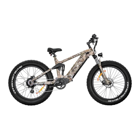
Page 4: Bike Specification
Bike Specification Power Switch Shimano Shift Lever LED Light Switch Information LCD Display Throttle Saddle Battery Head Tube Rear Brake LED Headlight Motor Front Fork Front Brake Real Derailleur Controller... - Page 5 82.6 Inch - Total Length 42.9 Inch - Handlebar Height 51.1 Inch - Wheelbase 30.3 Inch - Min Seat Height 37 Inch - Max Seat Height 19.7 Inch - Chain Stay Length 32 Inch - Standover Height 24 Inch - Top Tube Length 30.3 Inch - Wheel Diameter 5.1 Inch...
- Page 6 Battery Charger US standard 3.0 A smart charger 48V 20Ah Samsung/LG lithium battery Range 60-80 miles Controller 48V/22A Motor 750W brushless gear hub motor Display LCD display with USB charging Total Payload Weight 400 lbs 88 lbs Capacity Recommended Pedal Assist 5'3"...
-
Page 7: Bike Assembly Guide
Bike Assembly Guide Preparation Checklist ◆ Headlight Power cable Transformer Quick-release skewer Pedals Hex wrench Extra tools needed: (1)10mm Wrench (2)15mm Wrench NOTICE: Before assembling your bike, it’s recommended to remove the battery for the reasons outlined below: Determine if there’s battery drain or damage during shipping. Reduce the weight of the ebike to make it easier to maneuver the bike while assembling. -
Page 8: Recommended Torque Values
Recommended Torque Values Hardware Location Recommended Torque(NM) Handlebar 12-18 Stem 12-18 Saddle 12-18 Front Wheel(For bikes with bolts on front wheel) 15-22 Rear wheel 30-38 Bottom Bracket Parts 30-50 Pedals 28-33 Disk Mounting Bolts Disk Caliper Mount Crank Bolts 32-36 Rear Derailleur Cable Pinch Front Derailleur Clamp Saddle Post Clamp... -
Page 9: Assembly Instructions
Assembly Instructions Handlebar Installation(4mm Hex Wrench) ◆ Step 1: Loosen the bolts on your bike stem. Step 2: Center your handlebars and rotate them to align to the marking pointed to in the below image. Step 3: Tighten bolts to handlebar stem, but don’t tighten completely as you may want to further adjust the angle later to align more precisely. Test the positioning, and adjust the handlebar to your preferred angle. - Page 10 Front wheel (15mm Wrench) ◆ Step 1: Loosen the bolts of the protection bar of the front fork. Pull out the red pad, which is used to protect the hydraulic brake caliper. Step 2: Roll the wheel in between the front fork. Align the fork dropouts with the axle of the wheel hub, making sure the dropouts are fully seated on the axle. Also, ensure the brake rotor is properly inserted into the caliper.
- Page 11 Step 4: Install the quick-release skewer starting from the brake rotor side of the wheel, inserting the quick-release skewer through the hub, and then replacing the second cone spring on the other side. Ensure both springs are pointed narrow-side-in towards the wheel hub. Step 5: Tighten the thumb nut until the quick-release lever is held in line with the axle, and then use your palm of your hand to close the quick-release lever.
- Page 12 Step 6: Inflate the tires and make sure they have sufficient pressure for riding comfort and safety, not exceeding the limit specified on the sidewall. Step 7: Rotate the front wheel. Make sure to fully close the quick release skewer lever on the front wheel and check the wheel balance in Pedal Only Mode. If you notice the riding is imbalanced or the rotation of the front wheel makes noise, it means the bolts were not completely tightened or not aligned horizontally.
- Page 13 Headlight (4mm Hex Wrench & 10mm Wrench) ◆ Step 1: Loosen the bolts on the fork brace. While holding the nut with a 10mm wrench, unscrew the bolt with a 4mm hex wrench. Step 2: Align the bolt holes of both your front light and the front fender together with the hole on the fork brace, then reinsert the bolt through all holes and tighten the bolt with a 10mm wrench and a hex wrench.
- Page 14 Pedals Installation ◆ Make sure your pedals are installed on the correct side, as installing on the wrong side will damage the threads. Indicators for the right pedal (R) and the left pedal (L) can be found in two places: the stickers on the plastic cover, and the bottom of the pedal threads. Before you install the pedals, apply a small amount of waterproof grease onto the spindle.
- Page 15 Seat Adjustment ◆ Adjust the Seat Height: Open the seatpost quick release lever. Adjust the seatpost height by sliding the seatpost up or down to a height appropriate for your leg length and preferred riding position. Do not extend the seatpost beyond the minimum insertion marking etched onto the seatpost. WARNING: Overextending the seatpost can cause it to break or come off your bike, putting you at very high risk of serious injury or death.
- Page 16 Adjust the Seat Angle: Step 1: Loosen the seat adjustment bolt beneath the seat. Move the seat backward or forward and tilt to adjust the angle within the limit markings etched on the seat rail. Do not exceed the limit markings, to ensure the safety of yourself and the bike. Step 2: Tighten the seat adjustment bolt.
- Page 17 After Bike Assembly ◆ Please write down the serial numbers found on the head tube, battery and motor on the inside front cover of this manual to facilitate failure reporting. Make sure each letter and number is correct. Make sure you take down the Capital Letters here! Make sure you take down the Capital Letters here! Bike frame number Battery serial number...
-
Page 18: Safety Check
Safety Checklist Safety Check Basic Steps o Test front and rear brakes for proper function. o Ensure brake pads are not overworn and are correctly positioned in relation to rims. Brakes o Make sure brake control cables are lubricated, correctly adjusted and display no obvious wear. o Check that brake control levers are lubricated and tightly secured to handlebars. -
Page 19: Safety Precautions
Safety Precautions The following safety notes provide additional information on the safe operation of your E-bike and should be closely reviewed. Improper operation, or failure to confirm correct installation, compatibility, and maintenance of any component or accessory may result in serious injury or death. Before Riding ◆... -
Page 20: E-Bike Use And Care
E-Bike Use and Care The following table of contents provides general guidance on e-bike variable power assist settings and their effects on both range and performance. This content will apply broadly to most riders, but multiple factors will affect individual results including rider fitness, terrain, proper maintenance, etc. While we hopes and believes you will thoroughly enjoy your e-bike, no guarantees of universal performance characteristics for all owners can be given. - Page 21 ◆ Display Screen Power Output Battery Level Pedal Assist Level Motor Power Speed Lighting Indicator Speed Unit Function List (Check form 1 down below) Range / Time Unit Text Display TRIP Single mileage (km) ERROR 21 Abnormal Current Total mileage (km) ERROR 22 Throttle Fault RIDETM...
- Page 22 Start-up Procedure ◆ Press and hold the power button “ ” on the control panel for two seconds until the display comes on. Press the information button “ ” on the control panel to cycle through the display settings: odometer, trip meter, max speed, and average speed. MILE MILE MILE...
- Page 23 NOTICE: If the motor power ever becomes too strong for riders’ preference or sense of safety, simply apply the handbrake to cut off motor power completely. If the throttle assist seems accidentally engaged too easily, causing unwanted acceleration, simply apply the handbrake or lower the Pedal Assist level to 0 to disengage the throttle.
- Page 24 Pedal - Assist Adjustment ◆ The e-bike ships with standard Pedal Assist settings ranging from 0 (no assist) to 5 (maximum assist). To adjust, hold both “ + ” and “ - ” together for two seconds, bringing you to the trip meter reset screen described above. Then, hold both “...
- Page 25 The e-bike ships with the throttle set to accelerate the e-bike to a maximum speed of 25 mph. This can be adjusted higher, BUT please be mindful of local laws and regulations regarding maximum throttle speeds permitted. The brand is not liable for any consequences of rider misuse of maximum throttle speed adjustments.
- Page 26 Security Code ◆ To prevent theft or unauthorized use of your e-bike, you may set a security passcode to prevent use of the motor/electronics (though still permitting manual pedalling). Hold “ + ” and “ - ” together for two seconds, first bringing you to the trip meter reset screen described above. Then, hold “...
- Page 27 Display will then show “ PSd-n ” (no), press “ + ” to change it to “ PSd-y ” (yes) to turn the security passcode on. Press “ ” to confirm. Then, choose a 4-digit passcode of your preference. Press “ + ” and “ - ” to adjust numbers up/down. •...
-
Page 28: Battery Charging
Battery Charging Charging Procedure for On-bike Charging ◆ Step 1: Check the battery power indicator on your display. Step 2: Assemble the charger as shown in Figure 1 by inserting the plug (Plug 1) into the transformer. Plug 2 Plug 2 Plug 1 Plug 3 Figure 1... - Page 29 Charging Procedure for Off-bike Charging ◆ Step 1: Find the keys located on the handlebar (fig. 3) and cut tie to remove them. If you cut them from the handlebars, be careful not to damage any of the wires. Figure 3 Figure 4 NOTICE: Please keep your key and its spare in a safe place.
- Page 30 Step 2: Use the key to unlock the battery (fig. 5). While holding the battery with one hand, detach the battery by turning the release switch located on the underside of the frame (fig. 6). Figure 5 Figure 6...
- Page 31 Step 3: Check the battery status (fig. 8): Light Status Charging Status Red (on charger) Charging Green(on charger) Fully charged Yellow(on battery) 40%-60% power Red(on battery) 40%< power Figure 7 Figure 8 NOTICE: Please write down the serial number found on the battery beneath the barcode (fig. 7) on the inside front cover of this manual to facilitate failure reporting.
- Page 32 Step 4: Safest way to charge your battery- First, assemble the charger as shown in Figure 1 inserting the plug (Plug 1) into the transformer. Then insert the DC plug (Plug 2) into the battery charging socket. Last, insert the power plug (Plug 3: 110/220 volt plug) to the power socket. This order helps extend the battery life and effectively reduces battery damage caused by improper charging.
- Page 33 After Charging ◆ Please unplug the main power supply first by removing the plug from the power socket, then remove the DC port from the battery. You can then check the battery status on the display screen Hold the battery with one hand and turn the release switch with the other hand to install the battery. Lock the battery when finished to prevent theft. NOTICE: If your battery displays abnormal charging behavior, such as: •...
- Page 34 Before Riding ◆ Ensure that the battery has been properly secured to the bike before each use by grasping the battery pack and pulling upwards, testing the security of the pack. Battery Maintenance (48V 20AH Samsung/LG Lithium-ion battery) ◆ • Do not fully drain your battery. Turn off the power when the battery charge is low. •...
-
Page 35: Riding Modes
Cheetah can reach speeds of up to 28 miles per hour with throttle mode, which not only allows you to travel faster, but also reassures riders with extra power whenever needed, depending on traffic conditions and rider energy levels. If you are an adventurer who chases after speed and distance without... -
Page 36: Riding Limitations
PEDAL-ONLY ◆ In this mode, the E-bikes will perform like a normal bike, as you’ll be riding without any assistance from the motor. This mode is especially useful if you run out of battery, or are looking for more intensive resistance training. We suggest that you select a lower assistance level when you first ride your Bike. -
Page 37: Parking & Transport
2. Ensure your loads are properly secured and periodically check that nothing has loosened. 3. Plan your route accordingly when cargo is loaded on the Cheetah, considering hill climbing ability, steering, and braking. Also account for moderately reduced range when carrying extra cargo weight (or an additional passenger). -
Page 38: Safety And Care Instructions
Safety and Care Instructions To ensure safe riding conditions and maximize e-bike longevity, you must follow the guidelines outlined below: • To clean the e-bike, wipe the frame with a damp cloth soaked in a mild, non-abrasive, non-corrosive detergent mixture. Wipe or spray all unpainted parts with anti-rust treatment after being used in coastal areas or areas with salty air or water. -
Page 39: Maintenance
Maintenance Battery Maintenance (48V 20AH Samsung/LG Lithium-ion battery) ◆ Don't fully drain your battery. Turn off the power when the battery charge is low. Fully charge the battery after each use, no matter how much power is used. This will prolong the battery life. If the battery is not used for a long time, store the battery with a full charge and charge it once a month. -
Page 40: Brake Maintenance
Brake Maintenance ◆ Pad replacement: Pads should be replaced if they become contaminated or have less than 2.5mm thickness. (Metal plate & wear material) Before riding: Check the pads for wear or contamination. Check the hose for cracking, wear or deformation. Replace if necessary. Check if the brake system is operating correctly. - Page 41 CAUTION: Cleanliness is a very important part of any maintenance of the Tektro hydraulic disc brake. If the pads or rotor become contaminated with oil or if the hydraulics become contaminated with impurities, braking performance will be greatly impaired. Use only Tektro brake fluid with the Tektro hydraulic disc brake.
- Page 42 Step 5: Attach a section of plastic tubing with knurled silver bleed fitting to your syringe (supplied with bleed kit). Fill Syringe halfway with Tektro Mineral Oil. Hold the Syringe vertically with the tip up and tap out any air bubbles. Install the knurled silver bleed fitting (supplied with the bleed kit) into the caliper bleed port.
- Page 43 Step 8: Start filling the brake with new mineral oil by slowly pushing the syringe. Air bubbles may come out of the reservoir. Continue pushing fluid until you no longer see bubbles coming out of the tube .(See 4d) Step 9: Remove the plastic bag or collection bottle, section of tube, and knuried bleed fitting from the brake lever reservoir.
- Page 44 If there is lasered "5.0mm Pad" and (or) “2.3mm rotor only" or "E.2.3" on the caliper of your hydraulic disc brakes, please make sure to replace your brake pads and rotors according to the original setup of each model. You can find more information about 2.3mm rotors and 5.0mm pads on TEKTRO website. (See 4i).
Need help?
Do you have a question about the CHEETAH and is the answer not in the manual?
Questions and answers