
Summary of Contents for Standalone MC-DS
- Page 1 MID-COUR EV CHARGE MC-DS 60KW Standalone Fast Charger User Manual & Installation Instructions 60KW Model W84A99900117-RB4 COPYRIGHT © 2021 Reserves the right to make changes to this product without further notice.
-
Page 3: Table Of Contents
Applications �����������������������������������������������������������������������������������1 1� Basic User Interface ��������������������������������������������������������������������2 2. Specification ������������������������������������������������������������������������������3 2.1 Product Specification �����������������������������������������������������������3 2.2 MC-DS 60KW Version Description �����������������������������������������6 2�3 LED Indication and Operation Status ������������������������������������7 2�4 Dimensions �������������������������������������������������������������������������8 2�5 Direction of cooling Airflow �������������������������������������������������8 3� Installation Instruction ���������������������������������������������������������������9 3�1 Before Installation ���������������������������������������������������������������9... -
Page 4: Introductions
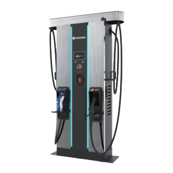
Introductions The Standalone DC Fast Charger is the top choice to power battery electric vehicles (BEV) and plug-in hybrid electric vehicles (PHEV). It is designed for quick charging in both public and private locations, such as retail and commercial parking spaces, fleet charging stations, highway service areas, workplace, residence, etc. -
Page 5: 1� Basic User Interface
1. Basic User Interface Antenna for Wi-Fi & 3G/4G LED Indication 7" Information Screen • Charging Status • Alarm information • User Authorization Right Button & Left Button RFID Card Reader Emergency Stop Left DC Connector Right DC Connector *The connectors installed on the EVSE may vary depending on the model (section 2.2) -
Page 6: Specification
2. Specification 2.1 Product Specification Model Name MC-DS 60KW Series Voltage Rating 3Φ480Vac (+10%,-15%) 78A @277Vac Max. Input Current 92A @235Vac Electrical Distribution 3P+ N+ PE (Wye configuration) Power Grid System TN/TT INPUT Frequency 50/60Hz Max. Input Power 67 kVA Power Factor >... - Page 7 Voltage Accuracy ±2% Current Accuracy ±2% Electrical Isolation Isolation between Input and Output Standby Power < 100W Ethernet, Wi-Fi and 3G or 4G LAN: support 10/10, 100/100 base Wi-Fi: support 2.4G DLWPH-8M (UL model): 4G Frequency Band: LTE FDD : B2/B4/B5/B12/B13/B14/B66/ 3G Frequency Band: External Communication...
- Page 8 Display 7-inch LCD Right Button : Select charging connector. Button Left Button : Home / Stop charge User Interface & RFID Support ISO 14443A/B, ISO 15693, Control FeliCa Lite-S (RCS966), User Authentication OCPP, 2D Barcode, APP, Mobile Payment Backend Support OCPP 1.6 JSON Operation -30°C to 50°C (-22°F to 122°F), power...
-
Page 9: 2.2 Mc-Ds 60Kw Version Description
2.2 MC-DS 60KW Version Description The MC-DS 60KW series are available in different versions depending on the charging connectors, below table shows the available combinations, the corresponding position of charging connectors are indicated from left to right when face to charger. -
Page 10: 2�3 Led Indication And Operation Status
2.3 LED Indication and Operation Status *Left LED for Left Connector, Right LED for Right Connector Standby Fault Charging Status Left Indicator Right Indicator Standby Green Green Fault Charging Blue Blue... -
Page 11: 2�4 Dimensions
2.4 Dimensions Main Size of Charger: (Unit: mm) 2.5 Direction of cooling Airflow Air Out Air In... -
Page 12: 3� Installation Instruction
3. Installation Instruction 3.1 Before Installation • Read all the instructions before using and installing this product. • Do not use this product if power cable or charging cable have any damage. • Do not use this product if the enclosure or charging connector are broken or open or if there is damage. -
Page 13: 3�2 Grounding And Safety Requirement
NOTICE It is recommended to conduct WI-Fi and 4G signal strength while charger installation. The RSSI (Received Signal Strength Indication) value is considered as good as higher than -65dBm. Poor connec- tion quality might interrupt charging process or data transaction. 3.2 Grounding and Safety Requirement •... - Page 14 480Vac (Line to Line) Three-Phase CAUTION! This is feed from Wye-connection power grid, the Standalone DC Fast Charger can connect to L1, L2 or L3, and Neutral. Earth ground must be connected to neutral at only one point, usually at the breaker panel.
-
Page 15: 3�3 Unpack The Charger
3.3 Unpack the charger 1. The product is direct current (DC) charger and the packing design passed the packaging simulation test. If the packaging damage caused by overturning, fall- ing or external impact during transportation, it may cause the product damage or defects. - Page 16 STEP 1� Remove the surrounding boards STEP 2� Remove the carton and packing cushion and film.
- Page 17 STEP 3� Remove these 4 pcs of fixing M12 screws. STEP 4� To use lifting eye bolts to move the EVSE, please apply 6mm (1/4 inches) di- ameter steel wire rope to the four eye bolts as following picture.
-
Page 18: 3�4 Recommended Tools For Installation And Inspection
3.4 Recommended Tools for Installation and Inspection 3�4�1 Recommended Tools for Installation Type Description Philips Screwdriver No. 2 and 3 Shifting Wrench Socket Screwdriver No. 8, 10, 17 and 19 Black / 15mm (0.6 ” ) Width Electrical Tape 53.5mm² (106 kcmil) at least Cable x 5 (L1, L2, L3, AC Input Cable N, PE)recommend 600V, 90 °... -
Page 19: 3�5 Installation Procedure
3.5 Installation Procedure 3�5�1 Required space for placing and maintaining Require a min. space of 1400x1531 mm(55.1x60.3 inch).This space is calculat- ed as follows: - Charger Size W x D x H:700 x 331 x 1800 mm(27.6x13.0x315.4 inch). - Front side 600 mm(23.6 inch),in order to operate dashboard. - Left and right side 350 mm(13.8 inch),in order to open left and right door. - Page 20 3�5�2 Build Concrete Base STEP 1� 1. Build 1020mm x 430mm x 200mm (40.16 ” x 16.93 ” x 7.87 ” ) concrete base on the level to stand charger in advance. 2. Implant AC input cable conduit smaller than Φ 80 mm (3.15 ” ), eg. Φ 2.5 ” PVC conduit;...
- Page 21 (For Ethernet cable conduit) (For AC cable conduit) (L Bracket orifice) screw stick (Front Direction) *Unit: mm(inch) STEP 2� • Extend 3 phase 5 wires AC input cables from conduit of concrete base, AC cables expose at least 400mm (15.75 ” ) and these 5 wires should be with ring terminals (L1, L2, L3 &...
- Page 22 3�5�3 Two Methods of Fixing DSWx601 Charger METHOD 1� Lift the charger on concrete base, pull the input cable through bottom hole of charger; fasten 8 pcs of M12 screw nuts and 4 pcs of M12 washers on 4 pcs of M12 screw of concrete base (2 nuts for each screw) to secure the chargers.
- Page 23 NOTE If remove the eye bolts on the top of the cabinet, must assemble the water- proof plastic bolts(in the accessory pack). 3�5�4 Installing Cables STEP 1� Open Right Cover for Wiring: Connect L1, L2, L3 and N of AC power to 4P termi- nal.
- Page 24 Do Inspection as section 3.6.1 to 3.6.3 . Turn on the power source and be ready for operational testing. The power supply of the Standalone DC Fast Charger will be enabled and automatically drive the information screen. Information screen will turn to Supplier charging solution screen within 30 seconds.
-
Page 25: 3�6 Installation Inspection & Commissioning
3.6 Installation Inspection & Commissioning 3�6�1 Environmental Check Item Status Remark Ambient Temperature Ambient Humidity Recommended but not Sunshade required. Recommended for better Rain Canopy charging experience and maintenance on rainy day. Installation Altitude < 2000m (6560 ft) Air Circulation / Drafty Dust Level Anti-Vandalism Measures 3�6�2 External Infrastructure Readiness &... - Page 26 3�6�3 Check – Static (Non-Powered) Item Status Remark Outlook Labeling & Warning Signs Package (Accessory) List Robustness of Input Wirings & Refer to 6.1 Screw torque connection requirement table 3�6�4 Check - Power On Item Status Remark Screen On Acoustic Noise Screen Display &...
- Page 27 3�6�5 Check - Charging Item Status Remark User Authorization –RFID User Authorization –QR Code User Authorization –Others. Waiting Time of Connection Check Reading of Each Display Item Full Charge Test Function of Electronic Lock Reading of Engineer Mode Airflow & Noise of Cooling Fan Charging Record ( log ) Upload Remote Control &...
-
Page 28: 4� Network Setting
4. Network Setting 4�1 Wi-Fi Network Setting • Laptop with RJ45 interface. • Connect RJ45 cable from Laptop to RJ45 charger ’ s RJ45 port. • Setup parameters in the Webservice. Step 1� Use the following IP address: Before opening web browser, please enter network setting to set your IPV4 IP address: 192 . - Page 29 Step 4� 192.168.1.10 Select Wi-Fi Module Network Select Wi-Fi modes and fill in SSID and Password Network Status according to your application, if not required, just Ethernet keep default. WiFi 3G/4G Wi-Fi Setting Description 192.168.1.10 UPGRADE OTHER LANGUAGE Wifi Ssid Service Set Identifier SSID WiFI Module Wifi...
-
Page 30: 4�2 3G/4G Setting
4�2 3G/4G Setting 4�2�1 SIM Card Installation Step 1� Open the right door. And you can see the 4G/Wi-Fi module inside the cabinet. Step 2� Insert 3G/4G Micro SIM Card in the tray, ensure the gold contacts are facing down and the notch is located in the upper right corner. - Page 31 4�2�2 Setting and Enable 3G/4G Module� Step 1� 192.168.1.10 • Please contact your SIM provider to get the login https://192.168.1.10 APN, PPP ID and password. Account admin *Note: PPP ID and password maybe options depend on your SIM provider. Password 1231231238 •...
-
Page 32: 4�3 Time Setting
4�3 Time setting Automatic setting : The time will be adjusted automatically when the charger connects to internet. Time server : time.windows.com • cn.ntp.org.cn • tock.stdtime.gov.tw • Note:Firewall and network environment may influence the time server connection Manual setting : Step 1�... - Page 33 Step 4� 192.168.1.10 SET -> Network. UPGRADE OTHER LANGUAGE System System Charging Network Backend Step 5� 192.168.1.10 System Click "System information". System Information Version Information Step 6� 192.168.1.10 Click system date time. System Click the calendar button on the right to set System Information the current time.
-
Page 34: 5� Operation Process
5. Operation Process 5.1 Operating Sequence • System Initialization • User Authorization • Plug in DC Charging Connector • Preparing for Charging • In Charging • Charging Terminated • Status Messages 5.2 Operating Procedure 5�2�1 System Initialization • When the charger is powered on, it start with the “ Charging Station ” Initializing page. - Page 35 Unit and currency if billing function is enabled • Ethernet Backend Status Connection Dis-Connection • Wi-Fi Status Connection Dis-Connection • 3G/4G Status Connection Dis-Connection • OCPP Backend Status Home page Connection Dis-Connection 5�2�2 User Authorization • After the system is initialized the screen will stay at Home page as below illustrated. •...
- Page 36 User authorizing User authorized. Authorization failed 5�2�3 Plug in Charging Connector • After authorization the screen will ask the user to plug the charging connector into the EV charging inlet as below illustrated. • Take the Charging connector from the charging cable holder and plug the con- nector into EV charging inlet.
- Page 37 5�2�4 Prepare for Charging • After authorization and plug-in process, the charger will start communicating with the vehicle and the screen will show the Preparing page as below illustrated. Information of Selected Charging Connector Connector Select Button Press right button to select the char- ger connector that the user would like to use.
- Page 38 • To start charging, load the charging information. When the battery has been fully charged or reaches the limit of the setting it will stop charging automatically and go to the next process. Press right button to select the charger connector that the user would like to stop.
- Page 39 5�2�6 Charging Terminated • After charging is terminated the charger system will show the Charging Summary page as below illustrated and the charging connector will auto- matically unlock. • Unplug the charging connector from charging inlet of the EV and return the charging connector to charging cable holder.
-
Page 40: 5�3 Troubleshooting
5.3 Troubleshooting • Please follow the instruction in the table when errors occur during the charging process. • Or please connect the EVSE to the Internet and then contact the EVSE provider for further instructions. • Please provide the EVSE information including serial number, model name, sta- tus code, failure behavior and timing, and also connect the EVSE to the Internet before remote diagnostics and upgrading •... - Page 41 Status Code Description 011021 WiFi module broken 011022 3G/4G module broken 011023 Aux. power module broken 011024 Relay control module /smart box broken 011025 CHAdeMO connector lock fail 011026 GB connector lock fail 011027 AC connector lock fail 011028 CHAdeMO module broken 011029 CCS module broken 011030...
- Page 42 Status Code Description 012212 System L1 input drop 012213 System L2 input drop 012214 System L3 input drop 012215 System AC output OVP 012216 System AC L1 output OCP 012217 System CHAdeMO output OVP 012218 System CHAdeMO output OCP 012219 System CCS output OVP 012220 System CCS output OCP...
- Page 43 Status Code Description 012244 Bluetooth module communication fail 012245 LCM module communication fail 012246 Aux. power module communication fail 012247 Relay control boaed/smart box communication fail 012248 CCS module communication fail 012249 CHAdeMO module communication fail 012250 GBT module communication fail 012251 Emergency stop 012252...
- Page 44 Status Code Description 012276 PSU Three Phase Input Inadequate 012277 PSU Three Phase Onput Imbalance 012278 PSU Ffc Side ShutDown 012279 NO PSU Resource 012280 Self test Failed due to communication of Relayboard failure 012281 Self test Failed due to communication of Fanboard failure 012282 Self test Failed due to communication of Primary failure 012283...
- Page 45 Status Code Description 012308 Psu Pfc And Dcdc Communication Fault 012309 Psu Bus Voltage Unbalance 012310 Psu Bus Over Voltage 012311 Psu Bus Voltage Abnormal 012312 Psu Bus Under Voltage 012313 Psu Input Phase Loss 012314 Psu Fan Full Speed 012315 Psu Temperature Power Limit 012316...
- Page 46 Status Code Description 013609 CCS Module fimrware update fail 013610 GB Module fimrware update fail 013611 Aux. power module fimrware update fail 013612 Relay control module fimrware update fail 013613 LCM module fimrware update fail 013614 Bluetooth module fimrware update fail 013615 WiFi module fimrware update fail 013616...
- Page 47 Status Code Description 023709 CHAdeMO: battery OTP 023710 CHAdeMO: battery current difference 023711 CHAdeMO: battery voltage difference 023712 CHAdeMO: shift position 023713 CHAdeMO: battery other fault 023714 CHAdeMO: charging system error 023715 CHAdeMO: ev normal stop 023716 CHAdeMO: connector temperature sensor broken 023717 CHAdeMO: connector lock fail 023718...
- Page 48 Status Code Description 023741 CCS_EVCC_EVErrorCode_FAILED_ChargingCurrentdifferential 023742 CCS_EVCC_EVErrorCode_FAILED_ChargingVoltageOutOfRange 023743 CCS_EVCC_EVErrorCode_FAILED_ChargingSystemIncompatibility 023744 CCS_EVCC_EVErrorCode_FAILED_EmergencyEvent 023745 CCS_EVCC_EVErrorCode_FAILED_Breaker 023746 CCS_EVCC_EVErrorCode_FAILED_NoData 023747 CCS_EVCC_EVErrorCode_FAILED_reserved_by_DIN_A 023748 CCS_EVCC_EVErrorCode_FAILED_reserved_by_DIN_B 023749 CCS_EVCC_EVErrorCode_FAILED_reserved_by_DIN_C 023750 CCS_EVCC_EVErrorCode_FAILED_reserved_by_ISO_1 023751 CCS_EVCC_EVErrorCode_FAILED_reserved_by_ISO_2 023752 CCS_EVCC_EVErrorCode_FAILED_reserved_by_ISO_3 023753 CCS_EVCC_EVErrorCode_FAILED_reserved_by_OEM_1 023754 CCS_EVCC_EVErrorCode_FAILED_reserved_by_OEM_2 023755 CCS_EVCC_EVErrorCode_FAILED_reserved_by_OEM_3 023756 CCS_EVCC_EVErrorCode_FAILED_reserved_by_OEM_4 023757 CCS_EVCC_EVErrorCode_FAILED_reserved_by_OEM_5 023758 CCS_SECC_ResponseCode_FAILED_SequenceError 023759 CCS_SECC_ResponseCode_FAILED_SignatureError 023760 CCS_SECC_ResponseCode_FAILED_UnknownSession...
- Page 49 Status Code Description 023773 CCS_SECC_ResponseCode_FAILED_ChallengeInvalid 023774 CCS_SECC_ResponseCode_FAILED_WrongEnergyTransferMode 023775 CCS_SECC_ResponseCode_FAILED_WrongChargeParameter 023776 CCS_SECC_ResponseCode_FAILED_ChargingProfileInvalid 023777 CCS_SECC_ResponseCode_FAILED_TariffSelectionInvalid 023778 CCS_SECC_ResponseCode_FAILED_EVSEPresentVoltageToLow 023779 CCS_SECC_ResponseCode_FAILED_PowerDeliveryNotApplied 023780 CCS_SECC_ResponseCode_FAILED_MeteringSignatureNotValid 023781 CCS_SECC_ResponseCode_FAILED_NoChargeServiceSelected 023782 CCS_SECC_ResponseCode_FAILED_ContactorError CCS_SECC_ResponseCode_FAILED_CertificateNotAllowedAtThi- 023783 sEVSE 023784 CCS_SECC_ResponseCode_FAILED_GAChargeStop 023785 CCS_SECC_ResponseCode_FAILED_AlignmentError 023786 CCS_SECC_ResponseCode_FAILED_ACDError 023787 CCS_SECC_ResponseCode_FAILED_AssociationError 023788 CCS_SECC_ResponseCode_FAILED_EVSEChargeAbort 023789 CCS_SECC_ResponseCode_FAILED_NoSupportedApp-Protocol 023790 CCS_SECC_ResponseCode_FAILED_ContractNotAccepted 023791 CCS_SECC_ResponseCode_FAILED_MOUnknown 023792...
- Page 50 Status Code Description 023800 CCS_SECC_ResponseCode_FAILED_CPS_Prov_CertificateRevoked CCS_SECC_ResponseCode_FAILED_CPS_SubCA1_CertificateRev- 023801 oked CCS_SECC_ResponseCode_FAILED_CPS_SubCA2_CertificateRev- 023802 oked CCS_SECC_ResponseCode_FAILED_CPS_RootCA_CertificateRev- 023803 oked 023804 CCS_SECC_ResponseCode_FAILED_reserved_1 023805 CCS_SECC_ResponseCode_FAILED_reserved_2 023806 CCS_SECC_ResponseCode_FAILED_reserved_3 023807 CCS_SECC_ResponseCode_FAILED_reserved_4 023808 CCS_SECC_ResponseCode_FAILED_reserved_5 023809 CCS_SECC_TIMEOUT_SLAC_TT_EVSE_SLAC_init 023810 CCS_SECC_TIMEOUT_SLAC_TP_match_response 023811 CCS_SECC_TIMEOUT_CM_START_ATTEN_CHAR_IND 023812 CCS_SECC_TIMEOUT_SLAC_TT_EVSE_match_MNBC 023813 CCS_SECC_TIMEOUT_SLAC_TP_EVSE_avg_atten_calc 023814 CCS_SECC_TIMEOUT_SLAC_CM_ATTEN_CHAR_RSP CCS_SECC_TIMEOUT_SLAC_CM_VALIDATE_REQ_1ST__CM_SLAC_ 023815 MATCH_REQ 023816 CCS_SECC_TIMEOUT_SLAC_TT_EVSE_assoc_session 023817 CCS_SECC_TIMEOUT_SLAC_TT_EVSE_vald_toggle...
- Page 51 Status Code Description 023829 CCS_SECC_TIMEOUT_SLACC_SDP_reserved_3 023830 CCS_SECC_TIMEOUT_SLACC_SDP_reserved_4 023831 CCS_SECC_TIMEOUT_SLACC_SDP_reserved_5 CCS_SECC_TIMEOUT_V2G_Msg_Performance_Time_Suppor- 023832 tedAppProtocolRes CCS_SECC_TIMEOUT_V2G_Msg_Performance_Time_SessionSet- 023833 upRes CCS_SECC_TIMEOUT_V2G_Msg_Performance_Time_ServiceDis- 023834 coveryRes CCS_SECC_TIMEOUT_V2G_Msg_Performance_Time_ServicePay- 023835 mentSelectionRes CCS_SECC_TIMEOUT_V2G_Msg_Performance_Time_ContractAu- 023836 thenticationRes CCS_SECC_TIMEOUT_V2G_Msg_Performance_Time_ChargePa- 023837 rameterDiscoveryRes CCS_SECC_TIMEOUT_V2G_Msg_Performance_Time_PowerDeliv- 023838 eryRes CCS_SECC_TIMEOUT_V2G_Msg_Performance_Time_CableCheck- 023839 CCS_SECC_TIMEOUT_V2G_Msg_Per formance_Time_Pre - 023840 ChargeRes CCS_SECC_TIMEOUT_V2G_Msg_Performance_Time_CurrentDe- 023841 mandRes CCS_SECC_TIMEOUT_V2G_Msg_Performance_Time_WeldingDe- 023842 tectionRes...
- Page 52 Status Code Description 023851 CCS_SECC_TIMEOUT_V2G_reserved_2 023852 CCS_SECC_TIMEOUT_V2G_reserved_3 023853 CCS_SECC_TIMEOUT_V2G_reserved_4 023854 CCS_SECC_TIMEOUT_V2G_reserved_5 023855 CCS_CAN_TIMEOUT_TP_GET_EV_TARGET_INFO 023856 CCS_CAN_TIMEOUT_TT_GET_EV_TARGET_INFO 023857 CCS_CAN_TIMEOUT_TP_GET_EV_BATTERY_INFO 023858 CCS_CAN_TIMEOUT_TT_GET_EV_BATTERY_INFO 023859 CCS_CAN_TIMEOUT_TP_EV_STOP_EVENT 023860 CCS_CAN_TIMEOUT_TT_EV_STOP_EVENT 023861 CCS_CAN_TIMEOUT_TP_EVSE_STOP_EVENT 023862 CCS_CAN_TIMEOUT_TT_EVSE_STOP_EVENT 023863 CCS_CAN_TIMEOUT_TP_GET_MISC_INFO 023864 CCS_CAN_TIMEOUT_TT_GET_MISC_INFO 023865 CCS_CAN_TIMEOUT_TP_DOWNLOAD_REQUEST 023866 CCS_CAN_TIMEOUT_TT_DOWNLOAD_REQUEST 023867 CCS_CAN_TIMEOUT_TP_START_BLOCK_TRANSFER 023868 CCS_CAN_TIMEOUT_TT_START_BLOCK_TRANSFER 023869 CCS_CAN_TIMEOUT_TP_DATA_TRANSFER 023870 CCS_CAN_TIMEOUT_TT_DATA_TRANSFER...
- Page 53 Status Code Description 023883 CCS_SECC_DIN_Msg_Decode_Error 023884 CCS_SECC_DIN_Msg_Encode_Error 023885 CCS_SECC_ISO1_Msg_Decode_Error 023886 CCS_SECC_ISO1_Msg_Encode_Error 023887 CCS_SECC_ISO2_Msg_Decode_Error 023888 CCS_SECC_ISO2_Msg_Encode_Error 023889 CCS_SECC_CP_State_Error 023890 CCS_SECC_Unexpected_60V_Before_Charing_Error 023891 CCS_SECC_Not_Ready_For_Charging CCS_SECC_TIMEOUT_QCA7000_COMM (The firmware code of 023892 QCA7000 may not be installed, yet) 023893 CCS_SECC_FAIL_QCA7000_SETKEY 023894 Reserved 023895 Reserved 023896 Reserved 023897 Reserved...
- Page 54 Status Code Description 023914 GBT_MOTHER_BOARD_MISS_LINK 023915 GBT_OUTPUT_VOLTAGE_MORE_THAN_LIMIT 023916 GBT_REQ_CURRENT_MORE_THAN_LIMIT 023917 GBT_OUTPUT_VOLTAGE_MORE_THAN_10_PERCENT 023918 GBT_OUTPUT_VOLTAGE_DIFF_BCS_5_PERCENT 023919 GBT_STOP_ADC_MORE_THAN_10V 023920 Reserved 023921 Reserved 023922 Reserved 023923 Reserved 023924 Reserved 023925 Reserved 023926 Reserved 023927 Reserved 023928 Reserved 023929 Reserved 023930 GBT_CEM_BHM_TIMEOUT 023931 GBT_CEM_BRM_TIMEOUT 023932 GBT_CEM_BCP_TIMEOUT 023933 GBT_CEM_BRO_TIMEOUT...
- Page 55 Status Code Description 023946 GBT_BEM_CSD_TIMEOUT 023947 GBT_BEM_BEM_OTHER_TIMEOUT 023948 Reserved 023949 Reserved 023950 GBT_BST_SOC_GOAL 023951 GBT_BST_TOTAL_VOLTAGE_GOAL 023952 GBT_BST_CELL_VOLTAGE_GOAL 023953 GBT_BST_GET_CST 023954 GBT_BST_ISOLATION 023955 GBT_BST_OUTPUT_CONNECTOR_OTP 023956 GBT_BST_COMPONEN 023957 GBT_BST_CHARGE_CONNECTOR 023958 GBT_BST_OTP 023959 GBT_BST_OTHER 023960 GBT_BST_HIGH_V 023961 GBT_BST_CC2 023962 GBT_BST_CURRENT 023963 GBT_BST_VOLTAGE 023964 GBT_GET_BST_NO_REASON 023965 Reserved...
- Page 56 Status Code Description 023978 023979 EV full charging 023980 ERROR_CODE_CHADEMO_BMS_CHARGE_ALLOW_ERROR ERROR_CODE_CHADEMO_OUTPUT_VOLTAGE_MORE_THAN_10_ 023981 PERCENT 023982 ERROR_CODE_CHADEMO_ADC_LESS_THAN_10V 023983 STOP by EV with unknow reason 033900 disconnected from backend through Ethernet 033901 disconnected from backend through WiFi 033902 disconnected from backend through 3G/4G 033903 Remote start charging by backend 033904...
- Page 57 Status Code Description 041036 Rotary switch fault 042200 System L1 input OVP 042201 System L2 input OVP 042202 System L3 input OVP 042203 System L1 input UVP 042204 System L2 input UVP 042205 System L3 input UVP 042206 PSU L1 input OVP 042207 PSU L2 input OVP 042208...
- Page 58 Status Code Description 042247 Relay control boaed/smart box communication fail 042251 Emergency stop 042252 Door open 042253 System fan decay 042254 Fail to create share memory 042255 CSU initialization failed 042257 MCU self-test Fault 042258 Relay self-test Fault 042262 System AC L1 output Circuit Short 042263 PSU Duplicate ID 042264...
- Page 59 Status Code Description 042286 Self test Failed due to communication of PSU failure 042287 Self test Failed due to Model name is none match 042291 Self test Failed due to communication of GBTboard failure 042292 Self test Failed due to communication of AC failure 042293 Self test Failed due to communication of Ledboard failure 042294...
- Page 60 Status Code Description 043602 Replace system air filter 043607 CSU fimrware update fail 043611 Aux. power module fimrware update fail 043612 Relay control module fimrware update fail 043614 Bluetooth module fimrware update fail 043615 WiFi module fimrware update fail 043616 3G/4G module fimrware update fail 043617 SMR fimrware update fail...
-
Page 61: 6� Maintenance
• If the enclosure or screen is broken, cracked, open or shows any other indication of damage then please contact the Standalone DC Fast Charger provider. WARNING: Danger of electrical shock or injury. Turn OFF power at the panelboard or load center before working on the equipment or remov- ing any component. - Page 62 Note: • Before switching off main breaker to begin maintenance, please record the sta- tus code number on the LCD monitor. • After maintenance door opened or NFB of charger turned off the charger is still hazardous. Only visual inspection can be operated. •...
- Page 63 Screw torque requirement table Screw in Metric Screw Steel Steel Steel Aluminum Aluminum Screw size type Inch-Lbs Kgf-Cm Kgf-Cm M2*0.4 Machine 3~4.77 3.5~5.5 0.34~0.54 3~4.5 0.34~0.44 M2.5*0.45 Machine 3~4.77 3.5~5.5 0.34~0.54 3~4.5 0.34~0.44 M3*0.5 Machine 5.5~9 6.5~10.5 0.64~1.04 5.2~8.4 0.51~0.82 M3.5*0.6 Machine 8.5~13 10~15...
-
Page 64: 6�2 Replacement Kits And Accessories
6.2 Replacement Kits and Accessories The DC EVSE offers the following replacement kits and accessories. Replacement Kit List 7-inch LCD CCS/CHAdeMO 125Amp (or above) DC charging connector & 4M charging cable Charging Cable Holder Emergency Stop Button 30kW DC PSU U-1K0100 MW Aux. -
Page 65: 7� Limited Product Warranty
7. Limited Product Warranty The warranty period of this charger is according to purchasing contract; two years typically. Any spare parts provided by Supplier and used as replacements for repair are cov- ered by a five-year guarantee. Replacement and repair parts manufactured by alternative manufacturers to those on the maintenance parts are only allowed if authorized by Supplier. - Page 66 Any remedy hardware product will be warranted for the remainder of the original warranty period or 90 days from delivery to the customer, whichever is longer. In order to receive the remedy set for above, you must contact Supplier during the warranty period and provide the model number, series number, proof of purchase, and date of purchase.
-
Page 67: Appendix - Package List
Appendix - Package list Item Description Remark EVSE User Manual EVSE Approved Certificate OQC Report RFID Card Door Key Waterproof Plastic Bolts Base Cover Cable Management Optional Bracket set for payment Optional system...
Need help?
Do you have a question about the MC-DS and is the answer not in the manual?
Questions and answers