Table of Contents
Advertisement
Reclosers
Types NOVA 15, NOVA 27, and NOVA 38;
Three-Phase Microprocessor-Controlled;
Installation and Operation Instructions
NOVA 15 for Serial Number 3421 and above
NOVA 27 for Serial Number 3268 and above
NOVA 38 for Serial Number CP571192790 and above
This bulletin is also applicable to product
serial numbers beginning with the prefix CP57.
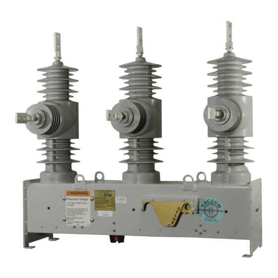
Figure 1.
NOVA three-phase, microprocessor-controlled recloser, shown with two-hole, flat-pad accessory.
Contents
Safety Information ..................................................... 2
Hazard Statement Definitions ................................. 2
Safety Instructions .................................................. 2
Product Information .................................................. 3
Introduction ............................................................ 3
Acceptance and Initial Inspection ........................... 3
Handling and Storage .............................................. 3
Standards .............................................................. 3
Description of Operation ......................................... 3
Ratings and Specifications ....................................... 4
Check Recloser Ratings Prior to Installation ........... 4
Dimensions ................................................................ 5
NOVA Mechanism Interface Options ....................... 6
Control-Powered Interface ..................................... 6
Auxiliary-Powered Interface ..................................... 7
Installation Procedure ............................................... 8
Moving the Recloser ............................................... 8
Lifting the Recloser ................................................. 8
Remove Recloser from Service .............................. 11
Grounding the NOVA Recloser ............................... 11
March 2011 • Supersedes 2/2011
S280-42-1
Operation ................................................................... 14
Electrical Operation ................................................ 14
OPEN/CLOSE Contact Position Indicator ............... 14
Internal Voltage Sensing Option .............................. 15
Accessories ............................................................... 19
Auxiliary Switch ....................................................... 19
Terminals ................................................................ 19
Pole-Mounting Hanger ........................................... 20
Arrester-Mounting Brackets ................................... 21
Substation-Mounting Frame ................................... 22
Service Information ................................................... 23
Service Requirements ............................................ 23
Frequency of Inspection ......................................... 23
Testing Operation ................................................... 23
High-Potential Withstand Testing ........................... 24
Module Flashover Service ....................................... 25
Troubleshooting ........................................................ 25
Unit Will Not Close ................................................. 25
Unit Will Not Open Electrically ................................ 25
Service Information
1
Advertisement
Table of Contents

Summary of Contents for Cooper Power Systems NOVA 15
-
Page 1: Table Of Contents
Reclosers Service Information Types NOVA 15, NOVA 27, and NOVA 38; S280-42-1 Three-Phase Microprocessor-Controlled; Installation and Operation Instructions NOVA 15 for Serial Number 3421 and above NOVA 27 for Serial Number 3268 and above NOVA 38 for Serial Number CP571192790 and above This bulletin is also applicable to product serial numbers beginning with the prefix CP57. -
Page 2: Safety Information
FOR LIFE FOR LIFE Cooper Power Systems products meet or exceed all applicable industry standards relating to product safety. We actively pro- mote safe practices in the use and maintenance of our products through our service literature, instructional training programs, and the continuous efforts of all Cooper Power Systems employees involved in product design, manufacture, marketing, and service. -
Page 3: Product Information
This recloser Standards is used in conjunction with a Cooper Power Systems The Type NOVA reclosers are designed and tested in microprocessor-based recloser control. accordance with: •... -
Page 4: Ratings And Specifications
Type NOVA Three-Phase, Microprocessor-Controlled Recloser Installation and Operation Instructions RATINGS AND SPECIFICATIONS Check Recloser Ratings Prior To Installation The recloser must be applied within its specified ratings. Check data plate ratings and compare with the system characteristics at the point of application prior to installa- tion. -
Page 5: Dimensions
(39.50) (16.25) NOTE: All dimensions are mm (inches). Dimensions shown are approximate. Terminal Options Eyebolt, 1/0 - 500 mcm 80 (3.25) NOVA 15 Cable Range (630 A maximum) 110 kV BIL (31.25) (20) Eyebolt, 4/0 - 1000 mcm 108 (4.25) -
Page 6: Nova Mechanism Interface Options
Serial Number Break for Control-Powered NOVA Reclosers with VTC Electronic Control Control-Powered NOVA Serial No. Recloser 120/240 VAC 19-Pin NOVA 15 100,000 or CP57####### Power Cable Control Cable NOVA 27 100,000 or CP57####### Figure 4. NOVA 38 100,000 or CP57####### Control-powered NOVA recloser configuration with potential transformer input power. -
Page 7: Auxiliary-Powered Interface
S280-42-1 SAFETY FOR LIFE Auxiliary-Powered Interface The charge on the capacitors will be maintained for the duration of the control battery power. Allow one minute The Type NOVA recloser mechanism with the auxiliary- between backup close operations to recharge the capaci- powered interface is fully operational with standard Cooper tors. -
Page 8: Installation Procedure
3. Install the recloser. Install the recloser in the appro- WARNING: This equipment is not intended to priate Cooper Power Systems pole- or substation- protect human life. Follow all locally approved mounting frame. Refer to Figure 7 for moving and lifting procedures and safety practices when installing or instructions. - Page 9 USE IT S280-42-1 SAFETY FOR LIFE CAUTION: Equipment misoperation. The control- WARNING: Hazardous voltage. Solidly ground all equipment. Failure to comply can result in death, powered NOVA reclosers that require a VTC interface must be used with VTC-ready controls. Failure severe personal injury, and equipment damage.
- Page 10 Type NOVA Three-Phase, Microprocessor-Controlled Recloser Installation and Operation Instructions 6. Make high-voltage line connections (refer to Figures Bypass 9 and 10). Switch Note: Disconnect switches and bypass switches are not required, but are highly recommended as they facili- tate switching and isolation. CAUTION: Equipment Damage.
-
Page 11: Remove Recloser From Service
T312.2 7. Disconnect the control cable from the recloser. 8. Follow standard utility procedures regarding removal of recloser from service. • Cooper Power Systems recommends transporting NOVA reclosers in the closed position to maximize the operational performance of the unit. - Page 12 Type NOVA Three-Phase, Microprocessor-Controlled Recloser Installation and Operation Instructions Grounding with a Local Supply Voltage Grounding with a Remote Supply Voltage Transformer: 4-Wire Multi-Grounded, Transformer: 4-Wire Multi-Grounded, 3-Wire Ungrounded, or Impedance- 3-Wire Ungrounded, or Impedance- Grounded Grounded Installation with a local supply voltage transformer must Installation with a remote supply voltage transformer must include the following (refer to Figure 11): include the following (refer to Figure 12):...
- Page 13 USE IT S280-42-1 SAFETY FOR LIFE Grounding on a 3-Wire Uni-Grounded System Installation on a 3-wire uni-grounded system must include the following (refer to Figure 13): CAUTION: Hazardous Voltage. Do not use a shared low-voltage network to power the recloser control •...
-
Page 14: Operation
Type NOVA Three-Phase, Microprocessor-Controlled Recloser Installation and Operation Instructions OPERATION Hotstick Operation (Manual Open, WARNING: This equipment is not intended to Electrical Close protect human life. Follow all locally approved proce- dures and safety practices when installing or operating this equipment. -
Page 15: Internal Voltage Sensing Option
S280-42-1 SAFETY FOR LIFE INTERNAL VOLTAGE SENSING OPTION Installation The internal voltage sensors use a resistive voltage divider to provide a low-voltage input to the NOVA recloser control. WARNING: This equipment is not intended to Refer to the Installation section of this manual for informa- protect human life. - Page 16 Type NOVA Three-Phase, Microprocessor-Controlled Recloser Installation and Operation Instructions CAUTION: Hazardous voltage. Do not touch the Internal Voltage receptacle connections of the control/voltage-sens- Sensor Receptacle ing cable. If the recloser is energized and the control/ voltage-sensing cable is disconnected from the recloser or the control, a voltage clamped at 250 VAC will be pres- ent at the receptacle.
- Page 17 12.2 m (40 ft.) 175.3° -5.7° -175.4° 12000.0 15.25 m (50 ft.) 174.7° -6.5° -174.6° Phase Shift, NOVA 27 and NOVA 15 with extended BIL Form 4D Form 5 Form 6 3.05 m (10 ft.) 175.9° -4.0° -176.0° 6.10 m (20 ft.) 175.3°...
- Page 18 Type NOVA Three-Phase, Microprocessor-Controlled Recloser Installation and Operation Instructions Form 4D and Form 6 Control Settings When programming either control, the PT connection must be set for a Wye connection. Also, the Phantom Phase fea- The Form 4D and Form 6 controls must be programmed ture must be disabled.
-
Page 19: Accessories
The eyebolt, flat-pad, and stud terminals are made of cop- have a continuous current rating of 10 A. Their interrupting per alloys. Cooper Power Systems recommends terminal ratings are shown in Table 10. connection to copper wires to optimize the electrical con- nection. -
Page 20: Pole-Mounting Hanger
Note: All dimensions are mm (inches). Dimensions shown are approximate. Stud Type, 1.125 - 12 threads 82 (3.25) (800 A maximum) Dimension B NOVA 15 110 kV BIL (31.25) NOVA 15 125 kV BIL (33.25) NOVA 27 125 kV BIL (33.25) -
Page 21: Arrester-Mounting Brackets
S280-42-1 SAFETY FOR LIFE Arrester-Mounting Brackets The arrester-mounting bracket accessory (Figure 23) can be bolted to the recloser frame and pole-mounting hanger for the addition of inboard and outboard arresters. The arresters are not included with the brackets. 12 (0.50) Mounting Bolt 323 Min. -
Page 22: Substation-Mounting Frame
76 (3) increments (38) (18) 19 (0.75) 1060 Mounting Hole (4) (21.75) (41.75) Terminal Options NOVA 15 110 kV BIL (31.25) (20) Eyebolt, 1/0 - 500 mcm 80 (3.25) Cable Range (630 A maximum) NOVA 15 125 kV BIL (33.25) (22.25) -
Page 23: Service Information
Testing Operation B. By a continuity check between the recloser terminals. This recloser is used with Cooper Power Systems micro- processor-based recloser controls. Refer to the control 4. To close the recloser contacts: operation manual. -
Page 24: High-Potential Withstand Testing
Type NOVA Three-Phase, Microprocessor-Controlled Recloser Installation and Operation Instructions High-Potential Withstand Testing TEST 2 TEST 1 PHASE TO PHASE PHASE TO GROUND The following equipment is required for this test: High-voltage test set – Must be capable of supplying suit- able voltages for determining the dielectric withstand capa- bility of the recloser. -
Page 25: Module Flashover Service
If the recloser does not pass Tests 1, 2, or 3, contact an authorized service center or your Cooper Power Systems Unit Will Not Close representative. - Page 26 Type NOVA Three-Phase, Microprocessor-Controlled Recloser Installation and Operation Instructions AUXILIARY SWITCH ACCESSORY C.T. PROTECTOR R3-C CIRCUIT BOARD GVA–197–1 R3-D CONTROL CABLE RECEPTACLE R3-A R1-G R3-B AØ CT R3-G R1-H BØ CT R3-H R1-K R3-E R1-J CØ CT R3-F "CTP" R3-L CURRENT TRANSFORMER R3-M R3-J...
- Page 27 S280-42-1 SAFETY FOR LIFE Microswitches shown with recloser "MS1" "MS2" "MS3" contacts OPEN and yellow handle N.O . N.C. N.C. in the UP position. R1-M R1-J R1-K R1-D "P1" Position R1-C Sensor R1-E "P8" ACTUATOR R1-F CIRCUIT BOARD "AB" R1-B R1-A "P2"...
- Page 28 SAFETY ©2011 Cooper Industries. All rights reserved. FOR LIFE Cooper Power Systems, Kyle, and NOVA are valuable trade- marks of Cooper Industries in the U.S. and other countries. You are not permitted to use Cooper trademarks without the prior written consent of Cooper Industries.
Need help?
Do you have a question about the NOVA 15 and is the answer not in the manual?
Questions and answers