Table of Contents
Advertisement
Quick Links
Advertisement
Table of Contents

Summary of Contents for Fleet Management MLT-400i
- Page 1 MLT-400i Installation Guide 11/18/2009 FMS MLT-400i Installation Guide 4.3...
-
Page 2: Notice
MLT-400i Installation Guide Notice This installation guide is published and copyrighted by Fleet Management Solutions (FMS). All information and specifications in this document are subject to change without notice. Nothing in this document is intended to create additional or separate warranties or guarantees. -
Page 3: Table Of Contents
Safety Considerations ................5 Determine the Best Location ..............5 Connect Power, Ignition and I/O MLT-400iO OBDII Connection ..............6 MLT-400i Three-Wire Connection ............... 6 MLT-400i/400iO I/O Connection ..............8 Securing the Unit Validate Installation ... -
Page 4: Introduction
Introduction This installation manual covers the installation of the MLT-400i and MLT-400iO. The MLT-400i/O includes a GPS receiver and a two-way satellite communications modem. Options include a built-in, on-board diagnostic interface (OBDII), an in cab Message Display Terminal (MDT) and ignition disable relay. -
Page 5: Install Antenna
Install Antenna Install Antenna The MLT-400i antennas combine GPS and Iridium satellite antennas. The ANTIR01 is a permanent mount (see Appendix A for additional information); ANTIR02 is a suction cup window mount antenna. Proper installation is critical to achieve optimum performance. -
Page 6: Connect Power, Ignition And I/O
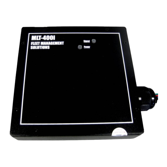
Connect Power, Ignition and I/O Connect Power, Ignition and I/O Two versions of the MLT-400i are available (check the product label located on the back of the unit to determine which one you have): 1) the MLT-400iO is OBDII compatible; 2) the standard MLT-400i uses a three-wire connection. - Page 7 7. Using a piece of electrical tape, wrap the connection and ½” of insulation on either side of the exposed wires. 8. Place a zip tie around the section where the bare wires are located under the electrical tape. 11/18/2009 FMS MLT-400i Installation Guide 4.3...
-
Page 8: Mlt-400I/400Io I/O Connection
4. Do not place the unit near moving parts, or next to any of the vehicle’s pedals 5. Loosely bundle any excess antenna cable, power wiring and unused I/O signals 6. Leaving easy access to the 9-pin serial cable will allow for code updating. 11/18/2009 FMS MLT-400i Installation Guide 4.3... -
Page 9: Validate Installation
If you have a Message Display Terminal (MDT) installed, you can begin the validation process by going to the System Status|Diagnostics Menu. The tests encompass the local connection between the MDT and MLT-400i, the Iridium signal strength, the GPS satellite count, as well as ignition wiring (and type), and the optional Ignition Enable/Disable feature. -
Page 10: Troubleshooting
Open a Support Ticket Admin|Support|Open Support Ticket E-mail: Contact FMS Technical Support at:(800) 999-2169 Phone: Contact FMS Technical Support at: techsupport@fmsgps.com. Mail: Fleet Management Solutions 3426 Empresa Drive, Suite 100 San Luis Obispo, CA, USA 93401 11/18/2009 FMS MLT-400i Installation Guide 4.3... -
Page 11: Appendix A - Antir01 Antenna Installation
.107" (#36) .107" (#36) Diameter Diameter 4 Places 4 Places GPS (Blue) GPS (Blue) .5937" (19/32) .5937" (19/32) Diameter Diameter Iridium (Black) Iridium (Black) .5937" (19/32) .5937" (19/32) Diameter Diameter 1.660" 1.660" 11/18/2009 FMS MLT-400i Installation Guide 4.3... - Page 12 MLT-400i Installation Guide Appendix A – ANTIR01 Antenna Installation 11/18/2009 FMS MLT-400i Installation Guide 4.3...
-
Page 13: Appendix B - Installation Checklist
Appendix B - Installation Checklist Appendix B – Installation Checklist Customer Single Unit Instal- lation Checklist Use this form to track which MLT-400i units are installed in Contact which vehicles. Indicates required information. FMS Technical Support at: (800) 999-2169 Phase 1 - Installation Information (To be completed by the installer) - Page 14 Customer Multiple Unit Installation Checklist Use this form to track which MLT-400i units are installed in which vehicles and to capture Odometer and Engine Hours (if available). This information will be entered into Fleet Central during the validation phase. Contact FMS Technical Support...
Need help?
Do you have a question about the MLT-400i and is the answer not in the manual?
Questions and answers