
Related Manuals for IED IEDA524-H

Summary of Contents for IED IEDA524-H
- Page 1 INSTALLATION INSTRUCTIONS IEDA524-H / IEDA520DTB DIGITAL MICROPHONE STATION IEDA524-H / IED0520DTB DIGITAL MICROPHONE STATION Installation Instructions REV: 12-12 DOC: 369B...
-
Page 2: Ordering Options
Just like IED’s other digital microphone stations, the 524 uses a single Ethernet interface for audio and control data. The 524 station is fully compatible with IEEE 802.3af standard for Power over Ethernet (PoE), allowing the 524 to be powered directly from any standard off-the-shelf PoE switch. -
Page 3: Network Requirements
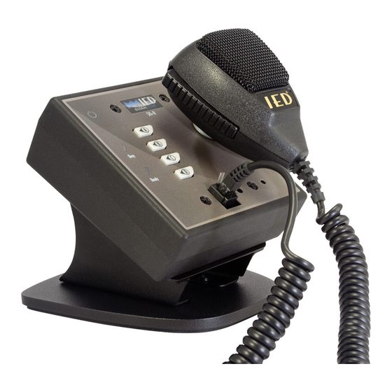
The 524 digital microphone station provides immediate digitization of full bandwidth audio and transmission over a standard Ethernet connection. It utilizes the IED 501HH teardrop handheld microphone that includes a programmable push-to-talk button. The station uses a metal magnet landing area for the 501HH to provide a storage position for the microphone. -
Page 4: Important Safety Instructions
IEDA524-H / IEDA520DTB DIGITAL MICROPHONE STATION INSTALLATION INSTRUCTIONS IMPORTANT SAFETY INSTRUCTIONS SAFETY SYMBOLS Read these instructions. Keep these instructions. Heed all warnings. Labeling on products and the Installation Instructions & Follow all instructions. User Manual may use safety related graphical symbols Do not use this apparatus near water. - Page 5 INSTALLATION INSTRUCTIONS IEDA524-H / IEDA520DTB DIGITAL MICROPHONE STATION CONNECTIONS Figure 1 - IEDA524-H Front View 1. Power LED This LED will illuminate when the microphone station is powered on. 2. Busy LED This red LED will flash if a button is pressed to make an announcement to indicate that the announcement cannot be made at this time because the system is busy.
- Page 6 IEDA524-H / IEDA520DTB DIGITAL MICROPHONE STATION INSTALLATION INSTRUCTIONS – Figure 2 - IEDA524-H Rear View 9. Ethernet Connector Use this RJ45 connector to connect the device to a PoE network switch using Category 5e or better cable. The PoE power consumption for the device is less than 2W.
-
Page 7: Installation
IEDA524-H Attached to Standard 2-Gang Electrical Box The IEDA524-H is designed to fit in a standard 2-gang electrical box. Install the unit into a box as shown in Figure 3. This is the preferred installation method for wall mounting or any other flush-mount applications. When this mounting method is used, you should remove the included plastic back box and store it for any future needs and use the included screws for mounting the device in the 2-gang electrical box. - Page 8 Alternative Single-Gang Electrical Box Installation The IEDA524-H is shipped with a plastic back box that can be used if the installation does not allow for the recom- mended 2-gang electrical box installation. This box can also be used if you later decide to mount the unit to a desktop base.
- Page 9 INSTALLATION INSTRUCTIONS IEDA524-H / IEDA520DTB DIGITAL MICROPHONE STATION Not Included Figure 6 - Alternate Single-Gang Electrical Box Method B Line Level Audio Output Connection If used, connect a balanced audio cable to the line level audio output connector using the supplied connector as shown in Figure 7.
- Page 10 IEDA524-H / IEDA520DTB DIGITAL MICROPHONE STATION INSTALLATION INSTRUCTIONS CONFIGURATION All microphone station operational functions are configured in the announcement controller software. You must correctly set the DIP switches on the microphone station so that it is correctly addressed on the network in order to communicate with the announcement controller.
- Page 11 INSTALLATION INSTRUCTIONS IEDA524-H / IEDA520DTB DIGITAL MICROPHONE STATION Mic Number DIP Switch Settings Switch REV: 12-12 DOC: 374B PAGE 10...
- Page 12 IEDA524-H / IEDA520DTB DIGITAL MICROPHONE STATION INSTALLATION INSTRUCTIONS Switch PAGE 11 DOC: 374B REV: 12-12...
- Page 13 INSTALLATION INSTRUCTIONS IEDA524-H / IEDA520DTB DIGITAL MICROPHONE STATION Switch REV: 12-12 DOC: 374B PAGE 12...
- Page 14 IEDA524-H / IEDA520DTB DIGITAL MICROPHONE STATION INSTALLATION INSTRUCTIONS Switch NOTE: The maximum total number of microphone stations supported in GLOBALCOM is 240. PAGE 13 DOC: 374B REV: 12-12...
- Page 15 Line Level Audio Output Enable Switch Line Output Enabled Line Output Disabled DIMENSIONS 1.907” .750” 4.952” .900” 1.812” 4.952” 3.281” Figure 9 - IEDA524-H 5.318” 5.128” 5.662” Figure 10 - IEDA524-H with optional IEDA520DTB REV: 12-12 DOC: 374B PAGE 14...
- Page 16 INSTALLATION INSTRUCTIONS IEDA524-H / IEDA520DTB DIGITAL MICROPHONE STATION Innovative Electronic Designs, LLC +1.502.267.7436 phone 9701 Taylorsville Road +1.502.267.9070 fax Louisville, KY 40299, USA www.iedaudio.com REV: 12-12 DOC: 374B ©2012, Innovative Electronic Designs, LLC...
Need help?
Do you have a question about the IEDA524-H and is the answer not in the manual?
Questions and answers