Table of Contents
Advertisement
Quick Links
Advertisement
Table of Contents

Subscribe to Our Youtube Channel
Related Manuals for Tecomec GEOline ECU1224


Summary of Contents for Tecomec GEOline ECU1224
-
Page 2: Table Of Contents
ISOBUS ECU 1224 User and Instruction maual 1 Sommario Sommario ............................1 INTRODUCTION ..........................4 LEGEND ............................4 INTENDED USE ..........................5 WARNINGS ............................ 5 PACKAGE CONTENT ........................7 Product description ....................... 7 Kit part number ........................8 ISOBUS ECU 1224 Sprayer Kit Contenent ................9 INSTALLATION SCHEME ...................... - Page 3 ISOBUS ECU 1224 User and Instruction maual 9.3.4 Pressure sensor setup ....................29 9.3.5 Tank level sensor setup ....................29 9.3.6 Sprayer geometry ......................30 9.3.7 Date-time from tractor TECU ..................30 WORK page .......................... 32 HISTORY page ........................35 HYDRAULIC CONTROL page ....................
- Page 4 ISOBUS ECU 1224 User and Instruction maual 13.3 Speed sensor ........................49 13.4 Level Sensor ......................... 50 SPARE PARTS ........................... 51 DIMENSIONS ........................... 52 TECHNICAL DATA ........................53 DECLARATION OF CONFORMITY ..................... 56 ISOBUS CERTIFICATION ......................57 WARRANTY ..........................58 19.1 Warranty periods ......................
-
Page 5: Introduction
2 INTRODUCTION Congratulations Dear User, You have chosen a product by Tecomec, a leading company in the development and production of electronic systems for agriculture. This manual provides information about operating and maintaining. For your safety and the safety of the people working with this equipment, it is very important that you read the manual carefully before using this system. -
Page 6: Intended Use
5 WARNINGS WARNING The power supply must be protected with fuse (10A recommended). If it is not the case, Tecomec s.r.l is not responsible for damages to ISOBUS ECU 1224. WARNING: Disconnect power supply cable ECU when battery is undergoing recharge. - Page 7 ISOBUS ECU 1224 User and Instruction maual WARNING: Disconnect power supply ECU before reparations, or welding procedure on the vehicle. If it is not the case, Tecomec s.r.l is not responsible for damages to the ECU. WARNING: For a correct functioning, please make sure that the battery voltage is higher than 10, 5 Volt.
-
Page 8: Package Content
ISOBUS ECU 1224 User and Instruction maual injuries. Safety practices reported in this manual do not override standard good practice. WARNING: Always check that any suspended vehicle attachments are lowered to the ground before beginning repair or maintenance work on a vehicle. WARNING: Wear appropriate protective clothing for the task being undertaken and conditions. -
Page 9: Kit Part Number
ISOBUS ECU 1224 User and Instruction maual the most modern tractors. Virtual Terminal can control any ISOBUS compatible implement. Can record data about production process and apply varying doses of plant protection products based on prescription maps using data from the navigation system (GPS) of the tractor. ISOBUS ECU 1224 regulate chemical quantity, assuring high protection at your crop. -
Page 10: Isobus Ecu 1224 Sprayer Kit Contenent
ISOBUS ECU 1224 User and Instruction maual Here reported codes for ordering Table 1 8410075 ISOBUS ECU 1224 SPRAYER from 2 up to 6W 2WIRES VALVE 8410074 ISOBUS ECU 1224 SPRAYER from 2 up to 7W 2 WIRES VALVE 8410073 ISOBUS ECU 1224 SPRAYER from 2 up to 9W 2 WIRES VALVE 8410076 ISOBUS ECU 1224 SPRAYER from 2 up to 11W 3 WIRES VALVE... -
Page 11: Installation Scheme
Main connection cable (C1) must be ordered separately according to the minimum length required. See chapter ACCESSORIES. Use only cables designed and produced by Tecomec for ISOBUS ECU 1224, the use of non-original parts invalidates the product warranty and does not guarantee the correct operation of the device 7.1.1 ISOBUS ECU 1224 Scheme up to 9 Sections... -
Page 12: Isobus Ecu 1224 Scheme Up To 9 Sections + Hydraulic
ISOBUS ECU 1224 User and Instruction maual Table 2 PART Description PART Description Driver ISOBUS ECU 1224 Pump ---------- Tank ---------- ---------- Speed sensor (Optional) Sprayer Boom Foam marker (Optional) Main cable Level Sensor (Optional) Gray connector valve cable Pressure sensor (Optional) Brown connector valve cable Electric valves ----------... -
Page 13: Isobus Ecu 1224 Scheme Up To 16 Sections
ISOBUS ECU 1224 User and Instruction maual Pressure sensor (Optional) Brown connector valve cable Electric valves ECU Hydraulic cable adapter 7.1.3 ISOBUS ECU 1224 Scheme up to 16 Sections Here below schematic connection for a 16 section valves sprayer with Hydraulic electric distributor. -
Page 14: Installation
ISOBUS ECU 1224 User and Instruction maual 8 INSTALLATION 8.1 ECU 1224 Installation ECU 1224 must be installed near electric valves in an area protected by accidental shock and reduced vibrations. Protect ECU 1224 by heat produced by implement 8.1.1 ECU 1224 Positioning Fix driver box on a flat surface applying 4 screws into the predefined holes. -
Page 15: Cables Connecting Isobus Ecu 1224
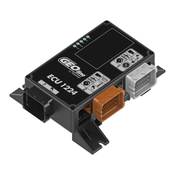
ISOBUS ECU 1224 User and Instruction maual 8.1.2 Cables connecting ISOBUS ECU 1224 Figure 7 Table 5 Connector Description Connector Description Black connector for ISOBUS main Brown connector for valves, cable connection flowmeter and optional sensors Grey connector for valves and optional sensors The cabling of Input sensors and Output need to be completed before the main cable is plugged to tractor. -
Page 16: Speed Sensor Installation
ISOBUS ECU 1224 User and Instruction maual Table 6 Power cable should be fixed to a support at a distance of at least 30cm from the connector itself to relieve the weight of the cable. Secure the cables with ties where possible. Repeat this operation for all the connectors of the driver box. -
Page 17: Tips For Installation
ISOBUS ECU 1224 User and Instruction maual Figure 9 The speed sensor is provided with a cable terminating with a 3-poles male connector, plug this connector in the female multi connector cable provided with the ISOBUS ECU 1224 . Sensor input plug is part of harness Connector C3 (Gray connector 24 pin), Label “S”... -
Page 18: Flowmeter Installation
ISOBUS ECU 1224 User and Instruction maual 8.3 Flowmeter installation The flowmeter is directly connected to ISOBUS ECU 1224 and measure flow in the control unit during a spraying treatment, it shall be correctly configured in the SETUP page of the user interface (refer to Flowmeter setup Chapter 9.3.2) The flowmeter shall be provided with a cable terminating with a 3-poles male connector, that will be plugged with the related female of the connection cable provided with ISOBUS ECU 1224. - Page 19 ISOBUS ECU 1224 User and Instruction maual product quantity currently contained in the tank, it shall be correctly configured in the SETUP page of the user interface (refer to sections 9.3 and 9.3.5). The tank-level sensor shall be provided with a cable terminating with a 3-poles male connector, that will be plugged with the related female of the connection cable provided with the ISOBUS ECU 1224.
-
Page 20: Check Hardware Installation
ISOBUS ECU 1224 User and Instruction maual 8.6 Check hardware installation Before plug ISOBUS ECU 1224 connector to ISOBUS PLUG installed on the tractor check the correct installation of each component: • Check that the connectors are in the right locations •... -
Page 21: Introduction
ISOBUS ECU 1224 User and Instruction maual 9.1 Introduction When ISOBUS ECU 1224 is connected to the tractor ISOBUS plug, shares its application data with the Virtual Terminal (VT) installed on the tractor cabin. Virtual terminal is the monitor, installed in the cabin. -
Page 22: Setup Page
ISOBUS ECU 1224 User and Instruction maual • (I): Software revision of Electronic Control Unit 9.3 SETUP page Figure 12 Figure 13 P00801545 Rev:02 SW:1.0.0... - Page 23 ISOBUS ECU 1224 User and Instruction maual Figure 14 The above setup pages contain all sprayer machine configuration parameters. Parameter configuration should be edited during electronic hardware installation. Only properly trained people should modify the contained configurations. All parameters entered are stored within the device's non-volatile memory. The keys on the right column have the following functions: Back to Home menu (A) Enter sections and Boom Menu (B)
- Page 24 ISOBUS ECU 1224 User and Instruction maual Table 12 Menu item Description Eligible range Speed Source Define which sensor used for speed Ground: from TC measurement of sprayer. Vehicle: from TC Tone Wheel: wheel sensor Simulated: simulated speed Tone wheel const (cm/imp) Number of cm per pulse, used for 1 ÷...
- Page 25 ISOBUS ECU 1224 User and Instruction maual ISO-15 ISO-20 Custom 1 Custom 2 Main valve type Type of main valve Bypass Dump Main valve driver How the main valve is managed Independent Dependent Regulation valve type Define what time of regulation valve Bypass (3 ways) is installed in the control unit Throttling (2 ways)
- Page 26 ISOBUS ECU 1224 User and Instruction maual (**) Connector distance Distance between wheel axis of the -100,00 ÷ 100,00 implement and Hitch point point (mm). In case of a three-point linkage this parameter must be 0. (**) Boom distance Distance of the bar from the wheel -100,00 ÷...
- Page 27 ISOBUS ECU 1224 User and Instruction maual on current flow rate Proportional coefficient of PID 0 ÷ 500 algorithm (Custom mode) Only technical operator should change this value User-settable PID supplementary 0 ÷ 500 coefficient (Custom mode) Only technical operator should change this value User-settable PID derivative (Custom 0 ÷...
-
Page 28: Section Width
ISOBUS ECU 1224 User and Instruction maual (**) These values could be read and used by the TC to automatically configure the geometry of the implement. However, they could also be completely overlooked. Editing SETUP page is allowed only when no treatment is running (it is assumed that a treatment is running when the main valve is open). -
Page 29: Speed Source Setup
ISOBUS ECU 1224 User and Instruction maual Figure 16 9.3.2 Speed source setup ISOBUS ECU 1224 can measure speed from different sources. In particular 4 sources can be selected: • Ground: the speed measure is received from the ISOBUS TC component (derived from GPS antenna) •... -
Page 30: Pressure Sensor Setup
The configuration page contains also the “flow-meter min/max value” parameters that are used by system for graphical and consistency check purposes. We recommend the use of Tecomec flowmeters having the following characteristics: Part No. l/1’ bar % FSO °C V dc... -
Page 31: Sprayer Geometry
ISOBUS ECU 1224 User and Instruction maual 9.3.6 Sprayer geometry For correct functions of automatic section control and ratio regulation edit correctly geometrical parameters related to the sprayer implement where it is mounted. The following image describes the meanings of each parameter. Figure 17 A. - Page 32 ISOBUS ECU 1224 User and Instruction maual When changing this parameter, ECU-1224 automatically reboot .In this case the following message will appear on the monitor and when the user confirms, the driver restarts and the new setting will be effective. Figure 18 When “Clock enable”...
-
Page 33: Work Page
ISOBUS ECU 1224 User and Instruction maual 9.4 WORK page From HOME page Figure 20 From HOME page Figure 21 P00801545 Rev:02 SW:1.0.0... - Page 34 ISOBUS ECU 1224 User and Instruction maual This user interface environment controls all the activities related to the execution of a treatment in the field. The function buttons available in this environment are listed below. Referring the above figures 20,21, representing the two pages according to the control mode selected (manual or automatic), the following screen areas are represented: During operation, the following information is shown in this environment: A.
- Page 35 ISOBUS ECU 1224 User and Instruction maual Left side boom sections opening. The opening logic depends on the current configuration of the “Sections control” setup parameter - standard or extended (refer to section 10.3 Table 11). • Standard: opening the last closed valve encountered from the left Example Figure 22 •...
-
Page 36: History Page
ISOBUS ECU 1224 User and Instruction maual Example Figure 25 Right side boom sections closing. The closing logic doesn’t depend on the current configuration of the “Sections control” setup parameter (standard or extended). Set the manual control mode. This button is available only when the automatic mode is currently active (refer to figure 21) Set the automatic control mode. -
Page 37: Hydraulic Control Page
ISOBUS ECU 1224 User and Instruction maual This page is the history of the latest treatments carried out. The following information is shown for each treatment: • Date/time of start of treatment. • Covered area (expressed in ha) • Sprayed volume (in liters) •... -
Page 38: Tank Calibration Page
ISOBUS ECU 1224 User and Instruction maual D. Open/close mechanical segments of the boom (maximum 6) – fold/unfold This feature requires an additional hydraulic control unit that can handle the driving valves. This control unit must be connected directly by ECU-1224. NB: This feature requires an additional ECU for electric hydraulic distributor 9.7 TANK CALIBRATION page From HOME page... -
Page 39: External Warning Lights Leds
ISOBUS ECU 1224 User and Instruction maual To define any additional calibration point, the key shall be pressed, while if there are no other points to be defined the key shall be pressed and the procedure ends confirming the points so far acquired. If the key is pressed at any time during the definition of the input calibration points, the procedure is aborted (the calibration data contained in the non-volatile memory are not updated). -
Page 40: Led L1: Main Status
ISOBUS ECU 1224 User and Instruction maual Following the description of LED Status Table 13 Status LED Light description Always turned OFF Always turned ON Flash Slow 1500 ms ON, 1500 ms OFF Flash Normal 700 ms ON, 700 ms OFF Flash Fast 250 ms ON, 250 ms OFF Pulse 1... -
Page 41: In Field Usage
ISOBUS ECU 1224 User and Instruction maual 10 IN FIELD USAGE ISOBUS ECU 1224 is dedicated to sprayer machine, and at least a Virtual Terminal device (VT), necessary to display the sprayer application user interface. The tractor ISOBUS network may also include a Task Controller device (TC), generally integrated in the terminal that implements the VT. -
Page 42: Switch-On/Off The Isobus Ecu 1224
ISOBUS ECU 1224 User and Instruction maual 10.2 Switch-On/Off the ISOBUS ECU 1224 ISOBUS ECU 1224 is automatically switched-on/off when the tractor is turned on/off. There is no physical switch on the ECU If the user turn-off the VT or disconnects it for any reason, the ISOBUS ECU 1224 automatically puts the sprayer to a safe-state represented by the closing of the main valve (if a treatment is running, it will be suspended). -
Page 43: Operating Modes
ISOBUS ECU 1224 User and Instruction maual The meaningful data related to the current treatment are always saved into the ISOBUS ECU 1224 non-volatile memory. indicators shown on the WORK page, display the data related to the last treatment suspended. They will be reset only starting a new treatment. ISOBUS ECU 1224 executes some checks before start/resume a treatment. -
Page 44: Automatic Mode
ISOBUS ECU 1224 User and Instruction maual • Define the Rate (liters/ha) set-point to be maintained during the treatment (can be manually changed during the spraying operation) • Define the sections of the boom to be open/closed All the above actions can be performed using the controls contained in the WORK page. 10.4.2 Automatic Mode This function shall be activated by the user only if your Virtual Terminal includes a Task Controller. -
Page 45: Main Valve Driver
ISOBUS ECU 1224 User and Instruction maual Figure 33 In this case the buttons are available, and the user can adjust the rate set point ( l/ha) 10.5 Main Valve Driver ISOBUS ECU 1224 driver allows the selection of the main valve operating mode (refer to parameter “Main Valve Driver”... -
Page 46: Dependent Mode
ISOBUS ECU 1224 User and Instruction maual The orange color is used for the section currently open, but not spraying because the main valve is closed (in the above case only the right left section is closed, and all the other open). When the user opens the main valve all the orange sections will start spraying and the grey ones will remain closed. -
Page 47: Historical Treatments
ISOBUS ECU 1224 User and Instruction maual If the tank level sensor is not installed, the user shall manually specify the new level of the tank. This can be done by pressing the key that causes the showing of a dialog box where the user can specify the new level. -
Page 48: Alarms
ISOBUS ECU 1224 User and Instruction maual 11 ALARMS 11.1 Introduction When the ECU-1224 detects an alarm situation, a red alarm icon and a message box describing the error type are shown in the WORK page. When the user acknowledges the error by confirming the message box, it is closed but the alarm icon persists until the alarm situation is not fixed. -
Page 49: Troubleshooting
ISOBUS ECU 1224 User and Instruction maual 12 TROUBLESHOOTING Table 14 DISPLAY CAUSE SOLUTION There is not power. Check the connections on the power cable. The display does not turn on The indicator is turned off. Press the turning on button. The valves can not be controlled The valves are not connected. -
Page 50: Accessories
ISOBUS ECU 1224 User and Instruction maual If the problem persists, call the technical support. 13 ACCESSORIES ISOBUS ECU 1224 can be equipped with these accessories: 13.1 Main cable Connection Cable between ISOBUS ECU 1224 and Tractor Table 15 Purchase Description Note CODE... -
Page 51: Level Sensor
ISOBUS ECU 1224 User and Instruction maual 13.4 Level Sensor Table 18 Purchase Description Note CODE Analogic level sensor Output: 3 wires 4-mA order Reseller apart cable C00902046 P00801545 Rev:02 SW:1.0.0... -
Page 52: Spare Parts
ISOBUS ECU 1224 User and Instruction maual 14 SPARE PARTS Here list of spare parts and purchase codes. All parts ECU and cables include label reporting Item code. Please verify code on your damaged part and place order using relative ordering code. Spare ordering code will include packaging and instructions for part handling. -
Page 53: Dimensions
ISOBUS ECU 1224 User and Instruction maual 15 DIMENSIONS Figure 39 Table 20 Dimension (mm) Notes: Recommended Cylindrical head screws with hexagon socket M6 P00801545 Rev:02 SW:1.0.0... -
Page 54: Technical Data
ISOBUS ECU 1224 User and Instruction maual 16 TECHNICAL DATA ECU features: Table 21 Parameter Description Unit ARM® 32-bit Cortex®-M3 CPU (120 MHz max) ECU Dimensions 110 x 180 x 45 Weight Connectors 3 x FCI: 24+24+24 Operating Temperature - 40 + 85 °C Supply Voltage 9 to 32... - Page 55 ISOBUS ECU 1224 User and Instruction maual Figure 40 Table 22 CONNECTOR DESCRIPTION BLACK PWR -VBATT ECU -VBATT ECU + VBATT ECU + VBATT CAN1-H CAN1-L PWR +VBATT All Other All other pins are RESERVED Table 23 CONNECTOR DESCRIPTION BROWN OUT 1 SECTION PIN SECTION PIN...
- Page 56 ISOBUS ECU 1224 User and Instruction maual SECTION PIN SECTION PIN SECTION PIN 12 Vdc valve (3 wires valve) All Other All other pins are RESERVED Table 24 CONNECTOR DESCRIPTION GRAY FLOW IN SIGNAL WHEEL SENSOR IN SIGNAL MAIN VALVE PIN MAIN VALVE PIN 12V PWR SENSOR REGULATION VALVE PIN...
-
Page 57: Declaration Of Conformity
ISOBUS ECU 1224 User and Instruction maual 17 DECLARATION OF CONFORMITY Figure 41 P00801545 Rev:02 SW:1.0.0... -
Page 58: Isobus Certification
ISOBUS ECU 1224 User and Instruction maual 18 ISOBUS CERTIFICATION Figure 42 P00801545 Rev:02 SW:1.0.0... -
Page 59: Warranty
This product has been designed and manufactured using the most modern techniques. The manufacturer guarantees the products for 24 months from the date of purchase. Tecomec S.r.l. guarantees that ISOBUS ECU 1224 SPRAYER labeled products are covered against manufacturing defects during the following periods. -
Page 60: Returning Goods
• The serial number must appear on the sales invoice to the final customer. • Repair and maintenance must be carried out only by Agres, Tecomec s.r.l. or authorized centers • As indicated in the Returning goods topic, the documentation must be correct for the equipment analysis to begin. -
Page 61: Quick Reference
ISOBUS ECU 1224 User and Instruction maual 20 QUICK REFERENCE 20.1 Switch-On/Off the ISOBUS ECU 1224 The ISOBUS ECU 1224 is automatically switched-on/off when the tractor is turned on/off. There is no physical switch on the ECU 20.2 Start new treatment Assuming that the ISOBUS ECU 1224 was correctly configured to start a new treatment the user Keep pressed valve key button, till a message box is shown requesting your OK (ENTER). -
Page 62: Ratio
ISOBUS ECU 1224 User and Instruction maual If the tank level sensor is not installed, the user shall manually specify the new level of the tank. This may be done by pressing the key that causes the showing of a dialog box where the user can specify the new level. - Page 63 ISOBUS ECU 1224 User and Instruction maual P00801545 Rev:02 SW:1.0.0...
- Page 64 ISOBUS ECU 1224 User and Instruction maual P00801545 Rev:02 SW:1.0.0...
- Page 65 ISOBUS ECU 1224 User and Instruction maual P00801545 Rev:02 SW:1.0.0...
- Page 66 ISOBUS ECU 1224 User and Instruction maual P00801545 Rev:02 SW:1.0.0...
- Page 67 ISOBUS ECU 1224 User and Instruction maual P00801545 Rev:02 SW:1.0.0...
- Page 68 ISOBUS ECU 1224 User and Instruction maual P00801545 Rev:02 SW:1.0.0...
Need help?
Do you have a question about the GEOline ECU1224 and is the answer not in the manual?
Questions and answers