
Subscribe to Our Youtube Channel
Related Manuals for flamco Logotherm LogoTronic Hub OTC

Summary of Contents for flamco Logotherm LogoTronic Hub OTC
- Page 1 Logotherm LogoT ronic Hub OTC for communication with LogoTronic controllers for electronically controlled interface stations (HIU) Operating instructions www.flamcogroup.com/manuals...
- Page 2 Acronyms Heat Interface Unit (interface station) Heating circuit return line Heating circuit flow line Flashing Wireless data transmission Firmware Domestic water, cold Remote Terminal Unit Ground External temperature sensor Manual LogoTronic Hub OTC...
-
Page 3: Table Of Contents
Table of contents Safety instructions ....................4 EU declaration of conformity ....................4 1.1.1 General instructions ........................4 1.1.2 Alterations to the equipment ......................4 Intended use ........................5 Warranty and liability ......................5 Disposal and hazardous substances ..................5 Description ....................... -
Page 4: Safety Instructions
Read the instructions carefully before installation and operation. The LogoTronic Hub OTC only works in conjunction with corresponding electronically controlled Flamco/Meibes interface stations. 1.1 EU declaration of conformity By affixing the CE mark to the equipment, the manufacturer declares that the LogoTronic Hub OTC is compliant with the relevant provisions:... -
Page 5: Intended Use
• Any equipment parts and accessory parts which are not in perfect condition must be replaced immediately. • Use only original replacement parts and accessories of the manufacturer. • You must not alter, remove or render illegible any labels on the equipment which have been affixed by the manufacturer. -
Page 6: Description
2. Description 2.1 Technical data Model LogoTronic Hub OTC Power supply 200 - 240VAC, 50 - 60Hz Power consumption 5W (power supply unit with electronics) Internal fuse 2A delayed Theory of operation Type I Degree of contamination Overvoltage category Permissible ambient conditions: in operation 0⁰C –... -
Page 7: Safety Symbols And Stickers
2.3 Safety symbols and stickers The LogoTronic Hub OTC is marked with the following symbols: 1. in the lower left corner of the transparent cover, the "High voltage" symbol and the "Read manual" symbol, see figure 2. on the inner cover plate to the right of the fuse holder and the word "FUSE": a sticker with the inscription "2A T", see figure... -
Page 8: Electrical Connections For The Logotronic Hub Otc
3.1 Electrical connections for the LogoTronic Hub OTC Example representations Legend: Pos. Identification Connection Comment Pin assignments L, N, PE, 230V Power supply Mains connection device: AC 230V, 50Hz EXT. TEMP Outside NTC, 10K resistor, Temp temperature for type see sensor (AT) Chapter 7.2.6 RS 485 COM... -
Page 9: Servicing
5. Servicing The equipment must be disconnected from mains power before any servicing is carried out! 5.1 Fuse A safety fuse is installed. The fuse installed is a 2A delayed fuse. The fuse type is: Glass fuse 5x 20 mm. Fuses may be changed only by specialist personnel once the equipment has been disconnected from mains power. -
Page 10: Keys A And B Components
6.1.1 Keys A and B components Each key can be operated by pressing and letting go, pressing and holding, and pressing and holding for a sustained period. Incident table Category Key -A- Key -B- Application mode Incident Prevents saving of the Press and let go All states (not booting) transfer log onto a USB... -
Page 11: Led Displays 1
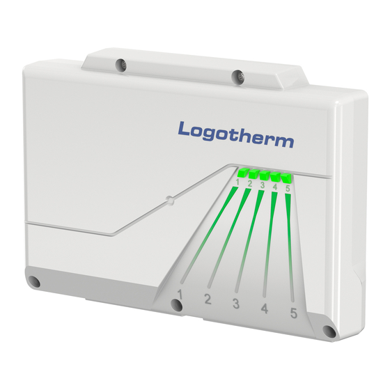
6.1.2 LED displays 1...5 The LEDs display the status. Each LED can be either "OFF", "ON", "Flashing slowly" (FLS) or "Flashing fast" (FLF): • Flashing slowly (FLS) means that the LED alternates between ON for 1 s and OFF for 1 s (flashing frequency of 0.5 Hz). -
Page 12: Logotronic Hub Otc - Functions
7. LogoTronic Hub OTC – functions 7.1 Modbus – General overview Modbus is a serial communication protocol used to transport data via serial channels between electronic devices. Modbus is an open protocol that can be used free of charge for commercial applications. -
Page 13: Remote Terminal Unit (Rtu) Mode
7.1.1 Remote Terminal Unit (RTU) mode Modbus protocol messages in Remote Terminal Unit (RTU) mode are transmitted in binary form from the transmitter to the recipient as serial RS-485 communication, for example. Transmitter Recipient Client Server Binary code, e.g.: 90 -> 01011010 (8 bits = 1 byte) (Master) (Slave) Recipient... -
Page 14: Uni-/Broadcast Transmission Principles
7.1.2.1 Uni-/Broadcast transmission principles In unicast mode, the client addresses an individual device which, after receiving the message, processes it and generates a response. The device address can vary from 1 to 247. A message always consists of a request and a response. If no response is received within a specified time, timeout is detected. In broadcast mode, the client sends a written command (request) to all participants on the bus, but they do not generate a response. -
Page 15: Modbus - Properties
7.1.4 Modbus – properties Properties of Modbus RTU in the client-server network Linear bus with bus termination: Network topology Cable with 120 Ohm resistance at both ends For connecting the devices, bus cables suitable for the respective application must be used and laid professionally, the cross-section must Transmission medium be AWG 26 (0.129mm²) or more. -
Page 16: Connection Of The Rs-485 Interface On The Circuit Board
7.2.1 Connection of the RS-485 interface on the circuit board Cable connection to RS-485: The CON29 is marked in the controller as "RS-485 COM" and counts the pin numbers from right (pin 1) to left (pin 4), see also Chapter 3.1 Pin assignment Pin description from right to left: 1) RS485-A 2) RS485-B... -
Page 17: Rs-485 Interface Settings (Notes For System Integrators)
4) The controller must be switched off and on again to activate the Modbus protocol. Note (for system integrators) on the Modbus client on PC: The program Flamco used to test the Modbus functionality is ModbusClientX https://sourceforge.net/projects/modbusclientx-modbus-tool/ 7.2.3 RS-485 interface settings (notes for system integrators) The factory settings of the Modbus interface are set to (8, N, 1, 9600Baud) by default: •... - Page 18 Send broadcast telegram: (Client -> server) Telegram Hex RTU structure Value Description Device address 0 1 0x00 Broadcast Function code 2 0x10 Function code for writing multiple holding registers Dates 0xAF 45002 Modbus register for outside temperature Dates 0xCA Dates 0x00 Number of registers to be read Dates...
-
Page 19: Client-Server Interconnection Options In The Modbus Network
7.2.5 Client-server interconnection options in the Modbus network Legend: Client, LogoTronic Hub OTC S1…Sn Server, LogoTronic controller for electronically controlled interface stations (HIU) Outside temperature sensor NTC 10K 120 Ohm – End resistors corresponding connection cables – provided by the customer We reserve the right to change designs and technical specifications of our products. -
Page 20: Notes On Components
7.2.6 Notes on components Components Example fig. To the outside temperature sensor: • included in the scope of delivery of the LogoTronic Hub OTC • NTC 10k resistor, Honeywell AF10-B65 • Operating range -40...70°C, IP54 • Art. no.: M10560.53 (for a spare parts case) Warning! The use of outside temperature sensors with other temperature characteristics, such as PT1000, is not possible here. - Page 21 We reserve the right to change designs and technical specifications of our products.
- Page 22 Manual LogoTronic Hub OTC...
- Page 23 We reserve the right to change designs and technical specifications of our products.
- Page 24 Copyright Flamco B.V., Almere, the Netherlands. No part of this publication may be reproduced or published in any way without explicit permission and mention of the source. The data listed are solely applicable to Flamco products. Flamco B.V. shall accept no liability whatsoever for incorrect use, application...
Need help?
Do you have a question about the Logotherm LogoTronic Hub OTC and is the answer not in the manual?
Questions and answers