
Summary of Contents for Kellfri 21-SV500B
- Page 1 21-SV500B SAWMILL Read this manual carefully before using the product! Translated from the original...
- Page 2 Table of contents Introduction Product information Intended use Safety information Product Safety information Instruction for emergencies Warning labels Personal Protection Surroundings Before use Installation instructions sawmill 9 - 21 Starting the engine Secure the log on the rail Sawing After use Transport and storing Maintenance and service 23 - 24...
-
Page 3: Product Information
INTRODUCTION Thank you for choosing a product from Kellfri AB. By following general safety information, operating instructions and common sense, you will have many years of enjoyable use of the product. Kellfris equipment and products are aimed to be use by active farmers with high demands on functionality. -
Page 4: Safety Information
Kellfri AB, Munkatorpsgatan 6, 532 37 SKARA Sweden. Tel.: +46 (0)511 242 50 (Pls. contact the retailer) https://www.kellfri.co.uk/ Do not use the equipment or product if you feel ill, tired or are under the influence of alcohol. -
Page 5: Product Safety Information
PRODUCT SAFETY INFORMATION • Read the instructions carefully before using the machine. • Fuel and fumes are flammable and explosive. Store fuel in an approved container and handle fuel with care. Do not store fuel or other flammable material nearby. Fires are prohibited near the machine. -
Page 6: Warning Labels
WARNING LABELS Make sure that the warning labels are always visible, clean the warning labels if necessary. Do not wash with high pressure washer directly on the warning label. If any part of the decal is worn or label becomes frayed or otherwise unreadable, order new decals. SYMBOL EXPLANATION Read the manual... -
Page 7: Personal Protection
PERSONAL PROTECTION Always wear suitable clothing and footwear. Do not wear loose clothing or jewelry when us- ing the machine. Remember to put up long hair when operating rotating machines. Wear pro- tective gloves, to prevent risking burns on contact with hot surfaces such as exhaust system, and to avoid oil and gasoline on the skin. -
Page 8: Before Use
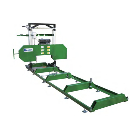
BEFORE USE Read the safety information and instruction manual carefully. Be sure you understand the safety measures, instruction manual and warning labels. Use common sense when operating the machine and use appropriate personal protective equipment. Always check the performance and the machine combination that are used. It’s highly impor- tant these matches in a satisfactory manner. - Page 9 INSTALLATION INSTRUCTIONS SAWMILL 1. Remove all packaging material, place the main unit standing (see picture below) on a flat surface. 2. Fit 2 square sections (# 30) in the fixing pipes on the main unit, left and right. Loosen the locking handle before mounting profiles (see pictures below) Table of contents...
- Page 10 (#30) (#30) 3. Take out all parts for the carriage (for a list of all parts See Figure I-II-III) Loosen the bolts with 16 mm wrench, then mount the feet on the square profile (# 30) Table of contents...
- Page 11 4. Loosen the bolts and mount the stabilizing frame (# 60) above the square profile. (#60) 5. Assemble (# 50) cranking bar (# 65), the nut is tightened with a 19 mm wrench. Fit the han- dle, tighten the nuts using 2x 13mm wrenches (see pictures below). Fit the bar on the stabi- liser bar, check that the crank is free, if necessary adjust the distance between bolts (# 62) and pole mount (# 64) (see pictures on next page) Table of contents...
- Page 12 Table of contents...
- Page 13 6. Mount the pawl (# 57) as shown below and mount the tension spring. (#57) Table of contents...
- Page 14 7. Tighten mountingbolts on the carriage 8. There are 2 wires (# 48) in the package, one long and one short. The long wire is mounted on the right side (right hook) of stabiliser and the short on the left (left hook) (position of right and left is determined when the operator is standing in front of the machine).
- Page 15 9. Loosen the locking handle (# 31) on each side, see pictures below. The carriage can now be adjusted up and down. Push up the latch and turn it forward or backward to raise or lower the carriage. 10. Adjust the carriage to make it straight. Crank up the carriage until the wires are tightened, Use a leveler to check which side of the trolley is higher or lower.
- Page 16 11. Assemble the frame (# 101) on the square profile, loosen the fixing bolts with 13mm span- ner and fit the frame. Then mount attachment for the water tank and bracket for the throttle control (# 105), see pictures below. Bolts are tightened with 16mm and 17mm wrench. (#101) Table of contents...
- Page 17 12. Mount the measuring scale (# 41), thread through the fixing holes and tighten. 13. Attach the water tank (# 98), as illustrated. Loosen the bolts (# 40) on the lower part of the main unit with 16mm wrench as shown in the pictures below and mount the copper pipe (# 92) located in the end of the water hose on the right side.
- Page 18 14 a.) Assemble the rail. Set the rails on a flat surface. The rails consist of two sections (standard delivery). The sections are aligned and bolted together into a track for the carriage. Fit 5 trans- verse log support but do not tighten the bolts yet. (see picture below) b.) Assemble the log clamp (# 146).
- Page 19 d.) Install the timber support (# 138, # 139) Use the appropriate support, long guides are suit- able for large logs and short guides are suitable for smaller logs. e.) Lubricate the thread and fit the locking pins. Table of contents...
- Page 20 f.) Install the adjustable feet (# 133). The track has 12 holes for mounting adjustable feet. g.) Install the mounting plate on the outside of the track, do not tighten the bolts yet. h.) Lift the saw carriage on the rails. Warning! saw carriage weighs a lot, were extreme caution when assembling the saw carriage to avoid damage.
- Page 21 i.) After putting the saw carriage on the rails, push the saw carriage ahead to see if it runs smoothly on the rails, adjust the height of the support feet if needed otherwise tighten all bolts. Check rail joint, it is important that both sections are in line with each other and that the rails are straight.
-
Page 22: Starting The Engine
Only people who understand the safety information and instructions in this manual may op- erate the equipment. Be alert and careful when working with the machine and only use the tool or product in the manner described in this manual. When working with equipment that has moving parts, there is always the risk of injury. -
Page 23: After Use
Check all bolts and nuts are tightened after maintenance and service. Always test the machine before work is started. • Lubricate moving parts regularly. For maintenance of the engine, see the separate man- ual. For parts: Contact Kellfri Service Table of contents... -
Page 24: Lubrication Of The Machine
Inspection It is very important to regularly check the machine, in order to detect and prevent wear and tear, damage, etc. WARNING! ALWAYS STOP THE ENGINE BEFORE STARTING MAINTENANCE /SER- VICE. TO AVOID UNEXPECTED START, TURN THE ENGINE TURN THE KEY TO “OFF” PO- SITION AND DISCONNECT THE SPARK PLUG CAP. -
Page 25: Troubleshooting
TROUBLESHOOTING PROBLEM PROBABLE CAUSE MEASURE The band saw blade breaks 1. The belt tension is insufficient. 1. Tighten the blade 2. Incorrect speed or feed rate 2. Increase the speed of the band saw 3. The log is loose on the rails blade and adjust the feeding speed, the 4. - Page 26 TROUBLESHOOTING PROBLEM PROBABLE CAUSE MEASURE The blade teeth are torn from 1. Wrong type of saw blade 1. Replace band saw blade, use only the the band 2. Incorrect feeding rate recommended band saw blade 3. The stock is loose 2.
- Page 27 INSTALLATION AND ADJUSTMENT OF SAW BLADE Instructions below must never be performed when the engine is running. For safety, remove the spark plug cap. Gloves and eye protection is recommended to use when working with the band saw. 1.) Loosen the 3 bolts with the 13 mm wrench and remove the protective cover. 2.) Loosen hex screw (# 91) on the blade guide blocks (# 90) on both the left and right side.
- Page 28 3.) Use gloves when mounting the blade.The blade teeth should be facing the operator. The blade rotates counterclockwise during operation. Fit the blade on band wheels, the lower part of the blade should mounted between the 2 band guides (# 90), tighten the blade. The teeth should be facing the operator 4.) Please note! It is important that the bolt (# 11) is in the center of the band wheel shaft (#...
- Page 29 a.) When the band wheel is skewed, left or right side is too close to the protective cover PICTURE 2 PICTURE 1 MEASURE: • Loosen the nuts (# 12) with a 24mm wrench shown in the pictures below. • If the wheel is skewed according to PICTURE 1: Loosen the adjustment bolt (# 11) tighten the bolt (# 1) until Tension ...
- Page 30 b.) Adjustment: Up and Down When the band wheel is skewed and the upper part (PICTURE 3) or lower part (PICTURE 4) of the wheel is too close to the protective cover. PICTURE 4 PICTURE 3 MEASURE If the band wheel is skewed as shown in PICTURE 3, loosen the top adjustment bolt (# 7) with the 19mm wrench and adjust it up until you have the correct height.
- Page 31 8.) Adjust the band guide (# 90), loosen the bolt M10x25 (# 40) with a 16mm wrench. Push the block so that the roller is against the backside of the band saw blade, the roller should not push the belt forward, because this affects the blade’s function. Adjust the blade so that it runs smoothly adjust if necessary, then tighten bolts.
- Page 32 BLUEPRINT I. CARRIAGE Table of contents...
- Page 33 BLUEPRINT II. SQUARE PROFILE BLUEPRINT III. THE CARRIAGE FEET Table of contents...
- Page 34 BLUEPRINT V. BAND WHEELS BLUEPRINT VI. RAILS Table of contents...
- Page 35 DESCRIPTION QTY. DESCRIPTION QTY. Adjustment handle Tension Block Plastic tray Coupling Socket Tension spring U-bracket Wedge Threaded rod Bearing 1641 RLD Bolt M12x150 Locking ring 52 Nut M12 Tension roller Spring washer 12 Plastic Washers 12 (12x4x45) Band Wheel shaft Allen screw 7 / 16-20x30 Washers The support holder såg-...
- Page 36 DESCRIPTION QTY. DESCRIPTION QTY. Carriage feet Throttle cable Bolt M16x80 Throttle Washers 16 Screw Spacer Washer 4 Locking ring 35 Lock Nut M4 Pulley Bolt M6x12 Bearings 6003 Lock nut M12 Lock nut M16 Hinge shaft Bolt M10x30 Split pin Measurement Scale Protective cover (left) Bolt M6x16...
- Page 37 DESCRIPTION QTY. DESCRIPTION QTY. Shaft Log Support (long) Spring Washer M8 Iron Plate - splicing Lock nut M8 Stabilisation Profile - splic- Attachment Nail Engine Bolt M10x50 Iron Profile Washers Stabilisation tube Clamp bushing - engine Log clamp Rivet 5x25 Flanged pin M10x25 Washer Table of contents...
- Page 38 EXTENSION OF RAIL (Optional 21-SVER) Extension Rail mounted as shown in the pictures below. Extension rails mounted in the center. Remove the existing cross bar (picture 1) and then install the extension rails and an additional cross bar that comes with the rails (picture 2). Important! check that the track is straight before tightening all bolts.
-
Page 39: Complaint Form
COMPLAINT FORM We are grateful for your help pointing out any inaccuracies in the Kellfri product delivered to you. Before making a complaint read Kellfris general warranty and sales conditions in our catalog as well as the enclosed User’s manual that comes with the machine. -
Page 40: Ec Declaration Of Conformity (Original)
You are always welcome to give your feedbacks, reviews or ask us about our equipment and products. Kellfri AB is constantly working on further developing their products and therefore reserves the right to modify, among other things the design and appearance without further notice.
Need help?
Do you have a question about the 21-SV500B and is the answer not in the manual?
Questions and answers