
Summary of Contents for Parvus DuraMAR 5915-2X
- Page 1 USER MANUAL ® Parvus DuraMAR 5915-2X Rugged Cisco 5915 Mobile Access Router combined with Cisco ESS‐2020 L2 Ethernet Switch MNL-0655-01 Rev A6 ECO-5592 Effective: 05 Feb 19...
- Page 2 Send us your comments and feedback: slp_feedback@curtisswright.com Trademarks Parvus is a brand of Curtiss-Wright Corporation. All trademarks, both marked and not marked, appearing in this document are the property of their respective owners. Copyright © 2015 Curtiss-Wright Page 2 of 40...
-
Page 3: Table Of Contents
User Manual, MAR-5915-2x Chapter 1 Introduction User Manual Table of Contents Chapter 1 Introduction ......................6 About This Document ............................ 6 Description of Safety Symbols ........................ 6 Functional Description ..........................7 Features ..............................8 Configurations ............................9 Block Diagrams............................. 10 Chapter 2 Operation ....................... - Page 4 User Manual, MAR-5915-2x Chapter 1 Introduction User Manual Shock ..............................37 Vibration ..............................37 Humidity ..............................37 Sealing ..............................37 Altitude ..............................37 EMI/EMC .............................. 37 Input Voltage ............................38 Chapter 5 Troubleshooting ....................39 Product Identification ........................... 39 Technical Assistance ..........................39 Returning for Service ..........................
- Page 5 User Manual, MAR-5915-2x Chapter 1 Introduction User Manual List of Figures Figure 1 – ROU ring cables......................... 11 Figure 2 – SWI ring cables* ........................11 Figure 3. Mounting Holes ........................... 20 Figure 4. Side Mounting Holes ........................21 Figure 5. Rear View ........................... 22 Figure 6.
-
Page 6: Chapter 1 Introduction
User Manual, MAR-5915-2x Chapter 1 Introduction User Manual Chapter 1 Introduction About This Document This document serves as a manual for the MAR-5915-2x products. The MAR-5915-2x systems comprise a MAR-5915-0x and a DUNET-30-2020-01 in one system. These two elements have separate manuals (MNL-0596A-01 &... -
Page 7: Functional Description
User Manual, MAR-5915-2x Chapter 1 Introduction User Manual Functional Description The MAR-5915-2X family combines the functionality of MAR-5915-0X and DuraNET 30-2020 by combining them in a single system. An internal connection links these two components. MAR-5915 port FE 0/4 is internally connected to ESS 2020 port FE 18. The 5915 router is physically housed in the DuraSTAX™... -
Page 8: Features
User Manual, MAR-5915-2x Chapter 1 Introduction User Manual Features Cisco Technology Integrated Cisco ESS 2020 Layer 2 IOS managed Ethernet switch with 19x Ethernet ports (2x GigE, 17x 10/100Base-T). Cisco IOS LAN Base images provide robust Layer 2 switching, management, security, and quality of service features ... -
Page 9: Configurations
User Manual, MAR-5915-2x Chapter 1 Introduction User Manual Configurations All MAR-5915-2X systems incorporate a Cisco ESS2020 with the Cisco LAN-Base IOS (equivalent to the standalone DuraNET 30-2020-01). The MAR-5915 Router portion is available with either a Base IOS or Advanced IOS. Advanced IOS versions can be ordered with optional CME license for 5, 25 or 50 users. Product Number Description DuraMAR 5915 Router w/ESS 2020 Switch(MAR-5915-00+DUNET-30-2020-01),... -
Page 10: Block Diagrams
User Manual, MAR-5915-2x Chapter 1 Introduction User Manual Block Diagrams Page 10 of 40 MNL-0655-01 Rev A6 ECO-5592 05 Feb 19... -
Page 11: Chapter 2 Operation
User Manual, MAR-5915-2x Chapter 2 Operation User Manual Chapter 2 Operation Breakout Cable Set A breakout cable set (CBL-MAR-5915-20) is available for the system. These cables are suitable for bench top testing and proof of concept setups. The same cable set works with all -2X models. Final installation should use custom cables designed for the target environment. - Page 12 User Manual, MAR-5915-2x Chapter 2 Operation User Manual The breakout cable set includes the cables listed in Table 1 Table 1 Cable Part # From Description CBL-2417-01 38999 (J1) Power. External power input cable. Banana 28V nominal voltage input. Red +, Black -, Green = Chassis Plug CBL-2418-01 38999 (J2)
-
Page 13: Quick Start Steps
A DC Power Supply with an output of between 12v and 36v (ideally 28v) Connections 1. Connect a power cable to port J1 on the DuraMAR 5915-2X (use CBL-2417-01 from the starter cable set, or an equivalent MIL-DTL-38999 power cable). -
Page 14: Ios Configuration
Chapter 2 Operation User Manual IOS Configuration The DuraMAR 5915-2X System is shipped with a Cisco factory-installed IOS on both the router and switch portions. Custom network configuration is the responsibility of the customer. This manual is not intended as a guide to the Cisco 5915, ESS2020 or IOS. -
Page 15: Zeroization
User Manual, MAR-5915-2x Chapter 2 Operation User Manual Zeroization Caution! The Zeroization function can delete all IOS and configuration files on the system! Zeroization should only be enabled if it is intended to be used. Enabling Zeroization for the Cisco 5915 (ROU) Prior to applying the zeroization signal, the Cisco IOS must be configured to enable zeroization. -
Page 16: Zeroization Recovery
User Manual, MAR-5915-2x Chapter 2 Operation User Manual Zeroization Recovery After zeroization has occurred you can perform the following steps to reload the system. Command Conventions Commands and arguments you must type are shown in bold. After you type the command, press the Enter key. ... -
Page 17: Loading The Rou Ios Configuration After Zeroization
User Manual, MAR-5915-2x Chapter 2 Operation User Manual 5. The IOS will begin transferring to the Cisco 5915. If the transfer does not begin, a message will be displayed explaining the problem. Fix the problem and repeat the tftpdnld command. 6. - Page 18 User Manual, MAR-5915-2x Chapter 2 Operation User Manual This transfer will take approximately 30 minutes. Once completed, you should get a prompt back to your switch: Begin the Xmodem or Xmodem-1K transfer now… C……………………………………………………………………. …………………………………………………………………….. File “xmodem:” successfully copied to “flash:c2020-universalk9-mz.150-2.EC.bin” switch: set BAUD 9600 Now, illegible characters will appear in the TeraTerm window when <enter>...
-
Page 19: Installation
User Manual Installation Orientation The DuraMAR 5915-2X can be mounted either vertically or horizontally and will perform equally well in either orientation. The target location normally dictates the mounting orientation. Choosing a Mounting Location – Thermal Considerations The DuraMAR5915-2X enclosure is highly efficient at removing heat from the inside of the unit to the outside of the finned enclosure. -
Page 20: Vertical Mounting
User Manual, MAR-5915-2x Chapter 2 Operation User Manual Vertical Mounting To install the DuraMAR5915-2X vertically on a mounting surface: 14. Create a hole pattern on the mounting surface that matches the pattern shown in Figure 3. The mounting holes are 0.27” in diameter. 15. -
Page 21: Horizontal Mounting
User Manual, MAR-5915-2x Chapter 2 Operation User Manual Horizontal Mounting To install the DuraMAR5915-2X on its side (horizontal): 1. Create a hole pattern on the mounting surface that matches the pattern shown in Figure 4. The mounting holes are 0.33” in diameter. 2. -
Page 22: Grounding
User Manual, MAR-5915-2x Chapter 2 Operation User Manual Grounding The bottom of the baseplate is conductive to allow the system to be grounded via the baseplate. A blind grounding hole for attachment of a grounding cable using a #1/4-20 bolt is provided on the rear of each ring of the system. -
Page 23: Chapter 3 Connector And Led Descriptions
User Manual, MAR-5915-2x Chapter 3 Connector and LED User Manual Descriptions Chapter 3 Connector and LED Descriptions This section identifies the pinouts and signal descriptions for the system, as well as connector part numbers along with suggested mating connector details. It also provides LED indicator descriptions. LEDs Figure 6. -
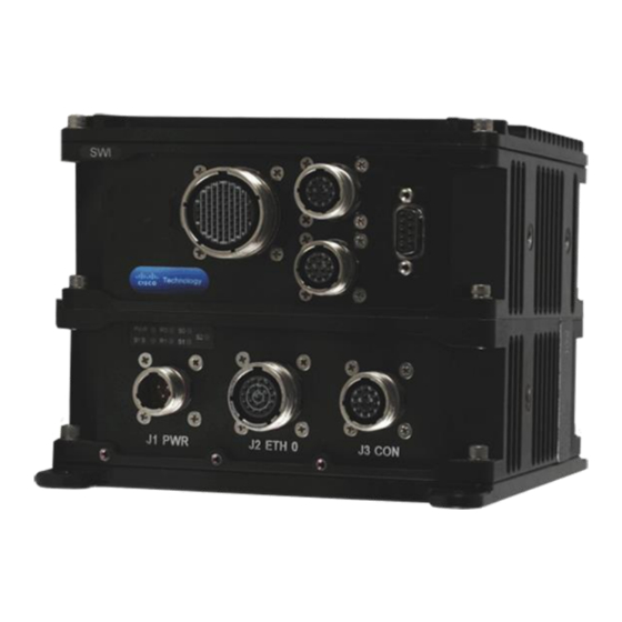
Page 24: J1 Pwr Pinouts
Chapter 3 Connector and LED User Manual, MAR-5915-2x Descriptions User Manual J1 PWR Pinouts J1 provides power input signals for +28V power to the Parvus Power Supply. P/N: D38999/20FA98PN (Shell Size 9) Figure 7. Connector J1 Power J1 Signal Name... -
Page 25: J2 Eth 0 Pinouts
User Manual, MAR-5915-2x Chapter 3 Connector and LED User Manual Descriptions J2 ETH 0 Pinouts J2 provides the signals for the Ethernet ports in the ROU ring. The ROU has five Ethernet ports, four of which are on J2. Connector Alignment: facing the insert side of the connector (pin side). -
Page 26: J3 Con Pinouts
Chapter 3 Connector and LED User Manual, MAR-5915-2x Descriptions User Manual J2 Signal Name Description 38999 Pin # .nc. Reserved .nc. Reserved SPARE_11 Populated spare SPARE_12 Populated spare J3 CON Pinouts J3 is the console connector for the Cisco 5915. Connector Alignment: facing the insert side of the connector (pin side). -
Page 27: Led Indicator Descriptions
User Manual, MAR-5915-2x Chapter 3 Connector and LED User Manual Descriptions LED Indicator Descriptions The table below describes the LEDs on the front panel of the base module. Component Description System power supply Blue light indicates power is on. Cisco 5915 Router Blinking green light indicates the boot-up phase or ROMMON monitor mode of the Cisco router. -
Page 28: Swi Ring
Chapter 3 Connector and LED User Manual, MAR-5915-2x Descriptions User Manual SWI ring Connector Identification and Mapping The following table shows the Cisco port mapping for each connector on the SWI Ring (identified in Figure 6). Connector Label Part Number Function Cisco Port Mapping Mating Connector... -
Page 29: J6 Eth/Con Pinouts
User Manual, MAR-5915-2x Chapter 3 Connector and LED User Manual Descriptions J6 ETH/CON Pinouts J6 has one Gigabit Ethernet port and one serial console port on its own circular connector. Four distinct twisted pairs of wire (eight wires) are required for gigabit transmission, and this documentation refers to these four pairs as pair Ax (Ax+, Ax-), pair Bx (Bx+, Bx-), pair Cx (Cx+, Cx-), and pair Dx (Dx+, Dx-). -
Page 30: J7 Eth2 Pinouts
Chapter 3 Connector and LED User Manual, MAR-5915-2x Descriptions User Manual J7 ETH2 Pinouts J7 is a Gigabit (10/100/1000Base-T) port. Four distinct twisted pairs of wire (eight wires) are required for gigabit transmission, and this documentation refers to these four pairs as pair Ax (Ax+, Ax-), pair Bx (Bx+, Bx-), pair Cx (Cx+, Cx-), and pair Dx (Dx+, Dx-). -
Page 31: J8 Eth3 Pinouts
User Manual, MAR-5915-2x Chapter 3 Connector and LED User Manual Descriptions J8 ETH3 Pinouts J8 has sixteen Fast Ethernet (10/100Base-T) ports all on the same circular connector. Only 2 distinct twisted pairs of wire are required for each port (4 wires per port), or 48 wires total (24 twisted pairs). This documentation refers to these pairs as pair TxN (TxN+, TxN-) and pair RxN (RxN+, RxN-), where N = a port number from 1 to 16. -
Page 32: J9 Con Pinouts
Chapter 3 Connector and LED User Manual, MAR-5915-2x Descriptions User Manual J9 CON Pinouts Caution! Do not connect to both console ports at the same time. J6 Console and J9 Console are the same port. Connecting to both ports will result in an electrical conflict on both connections. -
Page 33: Chapter 4 Specifications
User Manual, MAR-5915-2x Chapter 4 Specifications User Manual Chapter 4 Specifications Technical Specifications SWI Ring Cisco Technology Cisco ESS 2020 non-blocking OSI Data Layer 2 Ethernet switch-based (derivative of Cisco IE-2000) Software : Cisco IOS LAN Base image Ports ... -
Page 34: Rou Ring
User Manual, MAR-5915-2x Chapter 4 Specifications User Manual Quality of Service QoS: ingress policing, rate-limit, egress queueing/shaping, AutoQoS Layer 3 Routing IPv4 static routing ROU Ring Cisco Technology Integrated Cisco 5915 Embedded Services Router (ESR) PCI-104 Card ... -
Page 35: System
User Manual, MAR-5915-2x Chapter 4 Specifications User Manual Security Authentication: Route, PAP, CHAP, MS-CHAP Local Password, IP Access Lists, Time-Based Access Control Lists Generic Routing Encapsulation (GRE); Fast Switching, Cisco Express Forwarding, Process Switching, STAC Compression, RTP Header Compression ... -
Page 36: Figure 11. Front Panel Dimensions
Galvanic Isolation: 1500 VDC Dimensions Figure 3. Mounting Holes and Figure 11. provide the physical dimensions of the DuraMAR 5915-2X. Dimensions: 4.98” H x 6.75" D* x 6.25” W (~12.65cm H x ~17.15cm D x ~15.88cm W) *D= 8.25” including connectors & mounting tabs. -
Page 37: Environmental Specifications
User Manual, MAR-5915-2x Chapter 4 Specifications User Manual Installation: base flange mount or side boss mount (90° rotated orientation) Connectors: MIL-DTL-38999 Series III Cooling: passive natural convection. no moving parts Ingress protection: dust and water proof (similar to IP67) ... -
Page 38: Input Voltage
User Manual, MAR-5915-2x Chapter 4 Specifications User Manual Input Voltage Meets MIL-STD-704F,MIL-STD-1275D and DO-160G Section 16 Cat. A, Section 17 Cat. B and Section 18, Category R Page 38 of 40 MNL-0655-01 Rev A6 ECO-5592 05 Feb 19... -
Page 39: Chapter 5 Troubleshooting
Cisco Systems support is available to customers who have purchased a SmartNet account. This can be obtained directly from Cisco or from Parvus as part of an Extended Service Contract that also includes an extension of the standard hardware warranty period. In either case you need to provide the CSN (Cisco Serial Number) from the 5915 and ESS2020 in order to obtain coverage. -
Page 40: Chapter 6 Contact Info
Company contact info: Defense Solutions Division Curtiss-Wright 3222 S. Washington St. Salt Lake City, Utah, USA 84115 (801) 483-1533 FAX (801) 483-1523 Website: www.curtisswrightds.com/parvus Sales: +1(800) 483-3152 or (801) 483-1533 slp_sales@curtisswright.com Product Technical Support: +1 (801) 433-6322 slp_tsupport@curtisswright.com Customer Feedback: slp_feedback@curtisswright.com...
Need help?
Do you have a question about the DuraMAR 5915-2X and is the answer not in the manual?
Questions and answers