Table of Contents
Advertisement
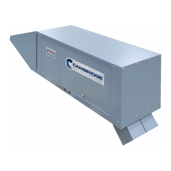
SA-SERIES
Direct Gas-Fired
Industrial Blow-Thru
Space Heater
®
Technical Manual
WARNING:
Improper installation, adjustment, alteration, service or maintenance can cause property
damage, injury or death. Read the installation, operating, and maintenance instructions
thoroughly before installing or servicing this equipment.
FOR YOUR SAFETY
The use and storage of gasoline or other flammable vapors and liquids in open containers in
the vicinity of this appliance is hazardous.
ASHRAE
ASHRAE
90.1
FOR YOUR SAFETY
If you smell gas:
1. Open windows.
COMPLIANT
COMPLIANT
2. Don't touch electrical switches.
3. Extinguish any open flame.
4. Immediately call your gas supplier.
Made in the USA
SA-TM3-0120
Advertisement
Table of Contents

Related Manuals for Cambridge Air Solutions Blow-Thru SA Series


Summary of Contents for Cambridge Air Solutions Blow-Thru SA Series
- Page 1 SA-SERIES Direct Gas-Fired Industrial Blow-Thru Space Heater ® Technical Manual WARNING: Improper installation, adjustment, alteration, service or maintenance can cause property damage, injury or death. Read the installation, operating, and maintenance instructions thoroughly before installing or servicing this equipment. FOR YOUR SAFETY The use and storage of gasoline or other flammable vapors and liquids in open containers in the vicinity of this appliance is hazardous.
- Page 2 LIMITED WARRANTY Cambridge Air Solutions (“Manufacturer”) warrants that its products (“the Products”) to be free from defects in material and workmanship. Manufacturer’s SA-Series Products shall be warranted for a period of 24 months from the date of shipment, except that burner assemblies are warranted for five years from date of shipment.
-
Page 3: Table Of Contents
Electrical Control Enclosure ..................35 Electrical Wiring Diagrams ...................36 Electrical Connection Diagram ..................38 Individual Component Descriptions ................39 ANSI/ASHRAE/IESNA Standard 90.1 ................42 Cambridge Air Solutions 760 Long Road Crossing Dr. Chesterfield, MO. 63005 Copyright © 2020 Phone: (636) 532-2233 Cambridge Air Solutions... -
Page 4: Hazard Summary
(e.g. when the heater is providing the make- up air to a boiler room), the unit is to be interlocked to open inlet air dampers or other such devices. If the heater is installed such that an inlet duct is Cambridge Air Solutions SA-Series Technical Manual... -
Page 5: General Installation Instructions
42". Adequate clearance of 42" for burner removal is also required. Access for installation is also recommended on the side of the unit opposite the control enclosure for a distance of 24". SA-Series Technical Manual Cambridge Air Solutions... -
Page 6: Typical System Overview
Under Roof Mounting ACCESSORY IDENTIFICATION Roof Top Mounting UNIT UNIT Thru Wall Mounting UNIT Thru Wall - Spiral Mounting Component Identification Adjustable Mounting Stand Discharge Duct Directional Elbows Inlet Collar Inlet Transition Mounting Curb Rain Hood Cambridge Air Solutions SA-Series Technical Manual... -
Page 7: Heater Operation
The heater drafts created by air infiltrating the building. will discharge air at the temperature selected (up to HEATER CONFIGURATION SA250 SA350 SA-Series Technical Manual Cambridge Air Solutions... -
Page 8: Roof Top Mounting
8. Install the directional elbows. Consult the job manufacturer’s recommendations. layout for the orientation of the elbows. Roof Opening Model Weight SA250 265 lbs. 48.25” 21.17” 8.5" 16" SA350 550 lbs. 65.5” 25.5” 13" 25" Cambridge Air Solutions SA-Series Technical Manual... - Page 9 SECURE MOUNTING STAND TO TIMBER WITH WOOD LAG INSULATION SCREWS AS SHOWN. MOUNTING STAND CONSTRUCTION: 12 GA. GALVANIZED STEEL ATTACH MOUNTING STAND TO UNIT ADJUSTABLE ±3.75" 2.5" 1.6" STAND DETAIL 22.5" 2 x 6 TREATED LUMBER (BY OTHERS) SA-Series Technical Manual Cambridge Air Solutions...
-
Page 10: Thru Wall Mounting
11. Install the directional elbows. Consult the job layout for the orientation of the elbows. Hanging Rods Wall Opening Model Weight Qty. Size SA250 220 lbs. 3/8" dia. 53" 23.16" 23" 23" SA350 550 lbs. 3/8" dia. 58" 33.25" 25" 27.5" Cambridge Air Solutions SA-Series Technical Manual... - Page 11 TYPICAL INSTALLATION THRU WALL MOUNTING HANGING BRACKET DETAIL HANGING ROD DETAIL HANGING ROD WASHER WASHER DOUBLE NUT SHIPPING POSITION HANGING RODS, NUTS AND WASHERS BY OTHERS SA250 SA350 SA-Series Technical Manual Cambridge Air Solutions...
-
Page 12: Under Roof Mounting
Consult local codes for additional references. Hanging Rods Model Weight Qty. Size SA250 220 lbs. 3/8" dia. 53" 23.16" SA350 550 lbs. 3/8" dia. 58" 33.25" Cambridge Air Solutions SA-Series Technical Manual... - Page 13 (BY OTHERS) DIRECTIONAL ELBOWS REMOTE CONTROL STATION/ THERMOSTAT CONTROLS ELECTRICAL CONTROL ENCLOSURE HANGING BRACKET DETAIL HANGING ROD DETAIL HANGING ROD WASHER WASHER DOUBLE NUT SHIPPING POSITION HANGING RODS, NUTS AND WASHERS BY OTHERS SA250 SA350 SA-Series Technical Manual Cambridge Air Solutions...
-
Page 14: Gas Piping
An adequate sediment trap must be installed start-up can result in damage to equipment and upstream of all gas controls for the heater and as components. close to the gas inlet connection of the heater as practical. Cambridge Air Solutions SA-Series Technical Manual... -
Page 15: Electrical Wiring
Electrical Code Article 725 or Canadian Electrical voltage does not agree with nameplate voltage, check Code C22.1 section 16 or local codes. with your local agent or Cambridge Air Solutions Customer Service Group at 1-800-473-4569 to 6. Connect the supply wiring to an electric determine what changes are required. -
Page 16: Start-Up Instructions
Read the following instructions carefully. Any not agree with nameplate voltage, check with your unauthorized modifications to, or deviations from these local agent or Cambridge Air Solutions Customer instructions will void warranty. Service Group to determine what changes are required. - Page 17 This will cause the burner to light on low fire and then fall to minimum fire. Manifold Pressure Reading = _______ " WC Turn the burner service switch to the “LOCAL” position. After a delay for prepurge and igniter SA-Series Technical Manual Cambridge Air Solutions...
- Page 18 7,500 ±250 Ω connected Turn the blower service switch to the “LOCAL” between terminals 21 and 22. The dial should be set position. Blower motor will start after the motorized to 160°F. damper (optional) opens. Cambridge Air Solutions SA-Series Technical Manual...
-
Page 19: Shutdown Instructions
If this occurs, the Discharge Temperature Sensor (DTS) will need to be Reset the thermostat to the desired space temperature. adjusted: SA-Series Technical Manual Cambridge Air Solutions... - Page 20 Carefully remove the DTS from the sampling box, turn it over and adjust the DTS calibration The Cambridge Air Solutions burner is for the most part potentiometer shown in the drawing. To raise the self-cleaning. However, if the application is extremely...
-
Page 21: Operating Instructions
10. Igniter is de-energized. 11. Low Fire Start is de-energized after 15 seconds. 12. Unit runs and modulates until operating thermostat and/or interlock opens (heater shuts off). 13. Steps (2) through (12) repeat themselves automatically as necessary. SA-Series Technical Manual Cambridge Air Solutions... -
Page 22: Tss Controller
OPERATING INSTRUCTIONS TSS CONTROLLER The Cambridge Air Solutions TSS Controller provides several features to tailor the operation of the Cambridge heating system to particular applications. • Seven day programmable clock. • Separate temperature settings for Heating and Setback operation. • Separate schedules for Summer Ventilation and Heating modes. - Page 23 SETTING AUTOMATIC ADJUSTMENT FOR DAYLIGHT SAVING TIME The TSS Controller has the ability to automatically detect and adjust for daylight saving time. The default setting on the controller is to recognize daylight saving time. SA-Series Technical Manual Cambridge Air Solutions...
- Page 24 "YES" if daylight DOWN saving time should be recognized or "NO" if daylight saving time is not recognized. 4. Press the button to exit SETBACK SCHEDULE/EXIT the scheduling program. Cambridge Air Solutions SA-Series Technical Manual...
- Page 25 TSS panel, will override the SETBACK temperature setting and increase the space temperature to the HEAT ON and HEAT OFF temperature settings for the amount of time set on the OVERRIDE timer. SA-Series Technical Manual Cambridge Air Solutions...
- Page 26 Off 10 On 11 On 11 Off 11 Off 11 On 12 On 12 Off 12 Off 12 On 13 On 13 Off 13 Off 13 On 14 On 14 Off 14 Off 14 Cambridge Air Solutions SA-Series Technical Manual...
- Page 27 ON time. DOWN 9. Press and bold the button while DAY OF WEEK pressing the or the button until the light DOWN for the desired day is illuminated. SA-Series Technical Manual Cambridge Air Solutions...
- Page 28 HED 7 SETBACK SCHEDULE/EXIT the scheduling program. HSD 8 HED 8 15. Verify that the correct current time and light for day HSD 9 of the week are still displayed. HED 9 Cambridge Air Solutions SA-Series Technical Manual...
- Page 29 DOWN desired holiday start date. 7. Press the button to exit SETBACK SCHEDULE/EXIT the scheduling program. 4. Press the button once to step to the first holiday end date cycle (HEd1). SA-Series Technical Manual Cambridge Air Solutions...
- Page 30 (A period [.] after the F will indicate the Calibration Mode). 2. Pressing the or the button will display the DOWN current calibration difference above or below (-) the measured temperature. Cambridge Air Solutions SA-Series Technical Manual...
-
Page 31: Troubleshooting Instructions
Improper voltage b) Consult factory c) Defective motor c) Replace motor 13. Blower a) Defective or locked bearings a) Replace or repair blower (SA250) Replace bearings (SA350) b) Physical damage b) Replace or repair blower SA-Series Technical Manual Cambridge Air Solutions... - Page 32 Clean or replace orifice b) No supply pressure b) Check all gas cocks and piping c) Improper manifold pressure c) Adjust regulator d) Defective regulator d) Replace regulator 7. Burner a) Defective burner a) Replace burner Cambridge Air Solutions SA-Series Technical Manual...
- Page 33 Increase differential temperature setting b) Open or short in thermistor circuit b) Check wiring or replace thermistor 4. Damper Motor End Switch (optional) a) End switch making intermittent contact a) Replace damper assembly SA-Series Technical Manual Cambridge Air Solutions...
- Page 34 1 and 3 or 2 and 3 exceeds 6,000Ω c) Sensor cross-wired to amplifier c) Correct wiring terminations d) Temperature Control System out of d) Perform appropriate calibration procedure calibration (page 17) Cambridge Air Solutions SA-Series Technical Manual...
- Page 35 3,500 Ω for the TS244A and 1,950 Ω for the TD244A 5. Multi-Functional PC Board a) Terminal X has power a) Determine power source b) Defective board b) Replace board SA-Series Technical Manual Cambridge Air Solutions...
- Page 36 Temperature control system out of b) Perform appropriate calibration procedure calibration (page 17) c) Defective amplifier c) Replace amplifier 3. Space Temperature Selector (CE-Smart a) Utilize shielded, twisted pair wiring a) Induced voltage in field wiring Cambridge Air Solutions SA-Series Technical Manual...
-
Page 37: Reference
REFERENCE ELECTRICAL CONTROL ENCLOSURE SA250 SA350 SA-Series Technical Manual Cambridge Air Solutions... -
Page 38: Electrical Wiring Diagrams
Motor Starter Service Switch - Heat Modulating Valve Exhaust Fan Contact Multi-Tap Transformer (24 & 120 Volt) Printed Circuit Board Flame Rod Class 2 Transformer (24 Volt) Flame Safeguard Relay (HSI) Temperature Sensor - LTC/EAT Cambridge Air Solutions SA-Series Technical Manual... - Page 39 Fuse 24 Volt Control Purge Timer Class 2 Transformer (24 Volt) Fuse 120 Volt Control R1A,B,C Relays - Gas Valve Temperature Sensor - LTC/EAT Hazardous Temp Stat Relay - Thermostat Control Temperature Setback System SA-Series Technical Manual Cambridge Air Solutions...
-
Page 40: Electrical Connection Diagram
REFERENCE ELECTRICAL CONNECTION DIAGRAM Cambridge Air Solutions SA-Series Technical Manual... -
Page 41: Individual Component Descriptions
500 feet using 18 gauge stranded, twisted-pair, setpoint by more than 3˚F, the modulating valve is driven shielded cable. to the MIN or MAX discharge temperature, as applicable. SA-Series Technical Manual Cambridge Air Solutions... - Page 42 DC response. design airflow of the heater. The resulting current flow produced can be measured with a DC microammeter. The reading should be steady and between 2.0 and 6.0 microamps (μA). Cambridge Air Solutions SA-Series Technical Manual...
- Page 43 3) The EAT (Entering Air Thermostat) circuit functions automatically to turn off the burner when the outdoor temperature reaches the EAT setpoint (45, 50, 55, 57.5, 60, 62, 64, 66, 68 or 70˚F). SA-Series Technical Manual Cambridge Air Solutions...
-
Page 44: Ansi/Ashrae/Iesna Standard 90.1
Units intended to operate continuously - No special controls are required to meet the standard. • Damper (Section 6.4.3.4.3) A damper is required on each heater. The Cambridge Motorized Inlet Damper (MID) will meet the standard. Cambridge Air Solutions SA-Series Technical Manual... - Page 45 MAINTENANCE LOG Model No:_____________ Serial No:_______________________ Date Activity Technician SA-Series Technical Manual Cambridge Air Solutions...
- Page 46 MAINTENANCE LOG Model No:_____________ Serial No:_______________________ Date Activity Technician Cambridge Air Solutions SA-Series Technical Manual...
- Page 47 Cambridge Air Solutions reserves the right to change specifications, modify the design and/or substitute equivalent materials without notice as the result of code requirements, product enhancements, ongoing research/development and vendor changes beyond our control.
- Page 48 760 Long Road Crossing Dr., Chesterfield, MO 63005 Phone: (636) 532-2233 (800) 899-1989, Fax: (636) 530-6133 www.cambridgeair.com...
Need help?
Do you have a question about the Blow-Thru SA Series and is the answer not in the manual?
Questions and answers