Endress+Hauser RIA46 Operating Instructions Manual
Hide thumbs
Also See for RIA46:
- Brief operating instructions (88 pages) ,
- Operating instructions manual (80 pages) ,
- Brief operating instructions (48 pages)

Related Manuals for Endress+Hauser RIA46


Summary of Contents for Endress+Hauser RIA46
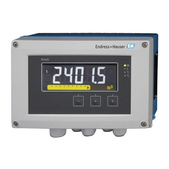
- Page 1 Operating Instructions RIA46 Field meter BA274R/09/en/04.09 71084133 SW Version 1.00.00...
- Page 2 RIA46 Brief overview For quick and easy commissioning: → ä 4 Safety instructions Æ → ä 7 Installation Æ → ä 10 Wiring Æ → ä 13 Display and operating elements Æ → ä 17 Commissioning Device configuration - explanation and use of all configurable device functions with the associated value ranges and settings.
-
Page 3: Table Of Contents
RIA46 Table of contents Table of contents Safety instructions ....4 Technical data ....39 Designated use . -
Page 4: Safety Instructions
Safety instructions RIA46 Safety instructions Safe operation of the device is only guaranteed if these Operating Instructions have been read and the safety instructions they contain have been observed. Designated use The device evaluates analog process variables and shows them on its multicolored display. Using the unit's outputs and limit relays, processes can be monitored and controlled. -
Page 5: Notes On Safety Conventions And Icons
RIA46 Safety instructions Notes on safety conventions and icons The safety instructions in these Operating Instructions are indicated by the following safety icons and symbols: " Caution! This symbol indicates an action or procedure which, if not performed correctly, can result in the incorrect operation or destruction of the device. -
Page 6: Identification
Identification RIA46 Identification Device designation 2.1.1 Nameplate Compare the nameplate on the device with the following diagram: a0010756 Fig. 2: Nameplate of the device (sample): A - Non-Ex version, B - Ex version Order code, serial number and ID number of the device... -
Page 7: Installation
RIA46 Installation Installation Incoming acceptance, transport, storage The permitted ambient and storage conditions must be observed. The precise specifications can be found in Section 10 "Technical data". 3.1.1 Incoming acceptance On receipt of the goods, check the following points: • Are the packaging or contents damaged? •... -
Page 8: Installation Procedure
Installation RIA46 Installation procedure The device can be mounted directly to the wall with 4 screws ∅5 mm (0.2") or the optional mounting plate can be used for wall or pipe mounting. a0010683 Fig. 3: Pipe mounting of the device... -
Page 9: Dimensions
RIA46 Installation Dimensions a0010574 Fig. 5: Dimensions of the device Drill-hole for direct wall mounting or on optional mounting plate with 4 screws ∅5 mm (0.2") Post-installation check • Is the sealing ring undamaged? • Is the device firmly screwed to the mounting plate or the wall? •... -
Page 10: Wiring
Wiring RIA46 Wiring Warning! Make sure that no voltage is supplied when wiring the device. " Caution! • The protective ground connection must be established before any other connection is made. A source of danger could arise if the protective ground connection is disconnected. - Page 11 RIA46 Wiring Overview of possible connection options at the device Terminal assignment of analog inputs, channel 1 and 2 a0010406 Connection of the transmitter power supply system 2-wire 4-wire a0010407 a0010408 Connection of the analog input RTD/resistance 2-wire RTD/resistance 3-wire...
-
Page 12: Post-Connection Check
Wiring RIA46 Connection of the power supply 24 to 230 V (-20%/+10%) 50/60 V AC/DC a0010746 Interface for configuring with the FieldCare PC software Note! No grounding conductor is connected for the plastic housing. For the aluminum housing, a grounding conductor can be connected at the grounding connection inside the housing. -
Page 13: Operating Elements And Display
RIA46 Operating elements and display Operating elements and display The easy operating concept of the device makes it possible for users to commission the device for many applications without a printed set of Operating Instructions. The FieldCare operating software is a quick and convenient way of configuring the device. Brief explanatory (help) texts provide additional information on individual parameters. -
Page 14: Display And Device Status Indicator/Led
Operating elements and display RIA46 Display and device status indicator/LED The device provides an illuminated LC display which is split into two sections. The segment section displays the value of the channel and additional information and alarms. In the dot matrix section, additional channel information, such as the TAG, unit or bar graph, is displayed in the display mode. -
Page 15: Icons
RIA46 Operating elements and display Icons 5.3.1 Display icons Device is locked/operating lock; the device setup is locked against changes to parameters, the display can be modified. Channel one (AnalogIn 1) Channel two (AnalogIn 2) First calculated value (Calc. Val 1) Second calculated value (Calc. -
Page 16: Quick Guide To The Operating Matrix
Operating elements and display RIA46 Quick guide to the operating matrix Display AI1 Reset AI2 Reset Cv1 Reset Cv2 Reset Analog In 1 Analog In 2 Calc 1 Calc 2 Contrast Brightness Alternating time Setup Application Analog In 1 Analog In 2... -
Page 17: Commissioning
RIA46 Commissioning Commissioning Post-installation check and switching on the device Make sure that all post-connection checks have been carried out before you commission your device: • ‘Post-installation check’ checklist in Section 3.5 • ‘Post-connection check’ checklist in Section 4.2 Once the operating voltage is applied, the display lights up and the green LED indicates that the device is operational. -
Page 18: Configuring The Device
Commissioning RIA46 Configuring the device Configuration steps: Select the application conditions (only for 2-channel devices) (→ Chap. 6.4.1) Configure the universal input(s) (→ Chap. 6.4.2) Configure the calculations (→ Chap. 6.4.3) Configure the analog output(s) (→ Chap. 6.4.4) Configure relays (if option selected); assign and monitor limit values (→ Chap. 6.4.5) Advanced device configuration (access protection/operating code;... - Page 19 RIA46 Commissioning Differential pressure application A concise setup is available for differential pressure applications. Once the differential pressure application setup has been successfully completed, the configured parameters of the analog inputs and the linearization points are used to automatically form the difference between the two inputs and linearize the signal.
- Page 20 Commissioning RIA46 ‘Setup’ menu item Setup É Application É ‘Diff pressure’ Preconfigured by application Submenu package Setup analog inputs ‘AI1 Lower range’: start of measuring range, analog input 1 (corresponds to 4 mA É Signal: ‘current’ for example) É Range: ‘4-20 mA’...
- Page 21 RIA46 Commissioning Limit values and relays are available for monitoring the measured values. They should be configured as described in Step 5 (→ Chap. 6.4.5). Setup AnalogIn 1 AnalogIn 2 Current Voltage RTD (resistance thermometer) TC (thermocouple) Deactivate the input Signal range Signal range (see Technical data);...
- Page 22 Commissioning RIA46 6.4.3 Step 3: Configuring the calculations One or two channels with the following functions are available for calculations: Calc Val 1 Calc Val 2 • Switched off • Switched off • Sum (AI1+AI2) • Sum (AI1+AI2) • Difference (AI1-AI2) •...
- Page 23 RIA46 Commissioning 6.4.5 Step 5: Configuring the relays, assigning and monitoring limit values The device has two limit values, which are either switched off, or can be assigned to the input signal or the linearized value of analog input 1 or 2 or the calculated values. The limit value is entered as a numerical value including the position of the decimal point.
- Page 24 Commissioning RIA46 Operating modes No action is triggered. The output assigned is always in the normal operating mode. Min (lower limit value) The limit value is active if the value configured is undershot. The limit value is switched off again if the limit value incl.
- Page 25 RIA46 Commissioning Gradient The "Gradient" operating mode is used to monitor the change in the input signal over time. The alarm is triggered if the measured value reaches or overshoots the set value. If the user configures a positive value, the limit value is monitored for rising gradients.
- Page 26 Commissioning RIA46 Inband The limit value is violated as soon as the measured value to be checked drops below or exceeds a minimum or maximum value specified beforehand. The hysteresis is located at the insides of the band. a0010192-en Fig. 13:...
- Page 27 RIA46 Commissioning 6.4.6 Step 6: Advanced device configuration (access protection/ operating code, saving the current setup) Access protection The access protection locks all the editable parameters, i.e. setup can only be accessed once the 4- digit user code has been entered.
- Page 28 Commissioning RIA46 Note! If several channels are active, the device switches automatically between the channels configured. Non-activated channels, calculated values and minimum and maximum values are called up manually by pressing the ‘+’ and ‘-’ keys and appear for 5 seconds on the display.
- Page 29 RIA46 Commissioning 6.4.9 Expert menu You activate the Expert mode by pressing ‘E’ É ‘Expert’ The Expert menu offers advanced device settings to be able to adapt the device optimally to the application conditions. An access code is needed to access the Expert menu. This code is preset at the factory as "0000". If a new access code is defined by the user, it replaces the access code assigned at the factory.
- Page 30 Commissioning RIA46 Failure mode If an error is detected at one of the two inputs, the internal status of the input is set to error. The behavior of the measured value in the event of an error can be defined here.
-
Page 31: In Operation
RIA46 Commissioning In operation 6.5.1 ‘+’ and ‘-’ quick pick keys You can use the ‘+’ and ‘-’ quick pick keys to switch through all the active channels (universal inputs and calculated values) in the display mode. The measured value or the calculated value is then displayed for 5 seconds. - Page 32 Commissioning RIA46 Measuring range limits Display Range - - - - - - - - - - Measured value - - - - - - - - - - - - - - - Special points to note Status Display...
- Page 33 RIA46 Commissioning 6.5.4 Saving diagnostic events/alarms and errors Diagnostic events such as alarms and fault conditions are saved in the device as soon as a new error occurs or the status of the device changes. The events saved are saved every 30 minutes to the nonvolatile device memory.
-
Page 34: Maintenance
Maintenance RIA46 Maintenance No special maintenance work is required on the device. Accessories Name Order No. Interface cable Commubox FXA291 FXA291 TXU10 TXU10 With plastic mounting plate (for pipes with ∅1-5 inches) 71089844 Pipe mounting kit Endress+Hauser... -
Page 35: Troubleshooting
RIA46 Troubleshooting Troubleshooting The following section provides you with an overview of possible causes of errors to provide you with an initial troubleshooting aid. Troubleshooting instructions Warning! The device cannot be operated in an open state for error diagnosis! Display... -
Page 36: Process Error Messages
Troubleshooting RIA46 Process error messages Note! Faults have the highest priority. The associated error code is displayed. 9.2.1 Device malfunction The errors are defined as: Error code Meaning F041 Sensor/cable open circuit F045 Sensor error F101 Range undershoot F102 Range overshoot... -
Page 37: Spare Parts
RIA46 Troubleshooting Spare parts a0011204-en Abb. 16: Spare parts of the device Item no. Designation Order no. Front metal incl. front foil and glass RIA46X-GB Front plastic incl. front foil RIA46X-GA Housing bottom part aluminium (metric threads) RIA46X-GD Housing bottom part aluminium (NPT1/2" threads) -
Page 38: Return
Troubleshooting RIA46 Item no. Designation Order no. Mainboard 24-230V (-20% +10%) 1 channel w/o relay, non Ex RIA46X-NA Mainboard 24-230V (-20% +10%) 1 channel w/o relay, EX RIA46X-NB Mainboard 24-230V (-20% +10%) 1 channel with relay, non EX RIA46X-NC Mainboard 24-230V (-20% +10%) 1 channel with relay, EX... -
Page 39: Technical Data
RIA46 Technical data Technical data 10.0.1 Input Inputs One or two universal inputs Measured variable Current, voltage, resistance, resistance thermometer, thermocouples Measuring ranges Current: • 0/4 to 20 mA +10% overrange • Short-circuit current: max. 150 mA • Load: 10 Ω... - Page 40 Technical data RIA46 10.0.2 Output Output signal One or two analog outputs, galvanically isolated Current/voltage output Current output: • 0/4 to 20 mA • Overrange up to 22 mA Voltage: • 0 to 10 V, 2 to 10 V, 0 to 5 V •...
- Page 41 RIA46 Technical data 10.0.3 Power supply Electrical connection a0010685 Fig. 17: Terminal assignment of the field meter Connection socket for interface cable Connection supply voltage Connection relay 1 (optional) Connection relay 2 (optional) Connection analog and status output Connection analog input 1 Connection analog input 2 (optional) ®...
- Page 42 Technical data RIA46 10.0.4 Performance characteristics Reference operating Power supply: 230 V AC, 50/60 Hz conditions Ambient temperature: 25 °C ± 5 °C (77 °F ± 9 °F) Humidity: 20 % to 60 % rel. humidity Maximum measured error Universal input:...
- Page 43 RIA46 Technical data AD converter resolution 16 bit Temperature drift: ≤ 0.01%/ K (0.1%/18 °F) oMR Temperature drift ≤ 0.02%/ K (0.2%/18 °F) oMR for Cu100, Cu50, Cu53, Pt50 and Pt46 Analog output: Current 0/4 to 20 mA, overrange to ±...
- Page 44 Technical data RIA46 Condensation permitted Electromagnetic compatibility (EMC) • Interference immunity: To IEC 61326 industrial environments / NAMUR NE 21 • Interference emissions: To IEC 61326 Class A 10.0.6 Mechanical construction Design, dimensions a0010574 Fig. 18: Dimensions of the field meter Drill-hole for direct wall mounting or on optional mounting plate with 4 screws ∅5 mm (0.2")
- Page 45 RIA46 Technical data 10.0.7 Human interface Display elements a0010690 Fig. 19: Display of the field meter 1: Channel display: 1: analog input 1; 2: analog input 2; 1M: calculated value 1; 2M: calculated value 2 2: Dot matrix display for TAG, bar graph and unit 3: Limit value indicators in the bar graph 4: "Operation locked"...
- Page 46 10.0.8 Certificates and approvals CE mark The device meets the legal requirements of the EU directives. Endress+Hauser confirms that the device has been tested successfully by affixing the CE mark. Ex approval Information about currently available Ex versions (ATEX, FM, CSA, etc.) can be supplied by your E+H Sales Center on request.
-
Page 47: Appendix
RIA46 Appendix Appendix The following tables show all the parameters available in the configuration menu. The values configured at the factory are marked in bold. 11.1 Further explanations on the differential pressure application at level measurement At both universal inputs pressure sensors are connected. - Page 48 Appendix RIA46 Conversion factors for various pressure engineering units: Pascal Technical Physical Torr Pounds per square Atmosphere Atmosphere inch (Pa) (bar) (at) (atm) (torr) (psi) ≡ 1 N/m ≡ 1 Mdyn/cm ≡ 1 kp/cm ≡ 1 pSTP ≡ 1 mmHg ≡...
- Page 49 RIA46 Appendix Calculation step: Calculation of the volume out of the height By means of the linearization of the calculated height value the volume can be calculated. This is done by assigning a certain volume value to every height value in dependency of the tank shape.
-
Page 50: Display Menu
Appendix RIA46 11.2 Display menu Display menu AI1 Reset Resets the minimum and maximum values saved for analog input 1. Only available if "Yes" was configured in the Setup>AnalogIn 1>Allow reset menu. AI2 Reset Resets the minimum and maximum values saved for analog input 2. -
Page 51: Setup Menu
RIA46 Appendix 11.3 Setup menu Setup menu Application Diff press Configures the application for the process display unit. 2-channel 2-channel is the default setting for two-channel devices, 1-channel for single- 1-channel channel devices. AnalogIn 1 AI1 Lower range Numerical value Configures the measuring range lower limit Only visible if É... - Page 52 Appendix RIA46 Setup menu Sign range 4-20mA, 4-20mA squar, Configures the input signal 0-20mA, 0-20mA squar, 0-10V, 0-10V squar, 0-5V, 2-10V, 1-5V, 1-5V squar, 0-1V, 0-1V squar, +/- 1V, +/- 10V, +/- 30V, +/- 100mV, +/- 150mV Pt46GOST, Pt50GOST, Pt100IEC, Pt100JIS,...
- Page 53 RIA46 Appendix Setup menu Sign range 4-20mA, 4-20mA squar, Configures the input signal 0-20mA, 0-20mA squar, 0-10V, 0-10V squar, 0-5V, 2-10V, 1-5V, 1-5V squar, 0-1V, 0-1V squar, +/- 1V, +/- 10V, +/- 30V, +/- 100mV, +/- 150mV Pt46GOST, Pt50GOST, Pt100IEC, Pt100JIS,...
- Page 54 Appendix RIA46 Setup menu No lin points 0 to 32 Number of points for linearization. X-value X-value 1 to X-value 32, For entering the points for linearization (max. 32) numerical value Y-value Y-value 1 to Y-value 2, For entering the points for linearization (max. 32)
- Page 55 RIA46 Appendix Setup menu Sign type 4-20mA Selects the type of signal for the output signal 0-20mA 0-10V 2-10V 0-5V 1-5V Lower range Numerical value Configures the measuring range lower limit Upper range Numerical value Configures the measuring range upper limit...
-
Page 56: Diagnostics Menu
Appendix RIA46 11.4 Diagnostics menu Diagnostics menu Current diagn Error code Displays the error code currently present Last diagn Error code Displays the last error code Operating time Numerical value Displays the hours operated up until now Diagnost logbook Diagnostics x... -
Page 57: Expert Menu
RIA46 Appendix 11.5 Expert menu In addition to all the parameters in the Setup menu, the following parameters are also available in the Expert mode: Expert menu Direct access 4-digit code By entering a 4-digit access code, you can go directly to a particular menu item. You can find the access codes in Section 5.4 "Quick guide to the operating matrix". - Page 58 Appendix RIA46 Expert menu Fixed fail value Numerical value The value configured here is output in Only visible if "Fixed value" was the event of an error. selected for the "Failure mode". Namur NE 43 Setting as to whether the failsafe mode is in accordance with NAMUR NE 43.
- Page 59 RIA46 Appendix Expert menu Calc value 1 Decimal places XXXXX Configures the number of decimal XXXX.X places for the display XXX.XX XX.XXX X.XXXX Failure mode Invalid Configures the failsafe mode Fixed value Fixed fail value Numerical value The value configured here is output in Only visible if "Fixed value"...
-
Page 60: Index
RIA46 Index Index Access protection ....... 27 Measuring range limits ......32 Analog output Min./max. - Page 62 www.endress.com/worldwide BA274R/09/en/04.09 71084133 FM+SGML6.0 ProMoDo...
Need help?
Do you have a question about the RIA46 and is the answer not in the manual?
Questions and answers