Subscribe to Our Youtube Channel
Summary of Contents for Advanced Axis AX AV-V70
- Page 1 AV-V70 Universal Audio Converter Installation, Operation & Programming Manual www.advancedco.com...
-
Page 2: Table Of Contents
Table of Contents Page INTRODUCTION ..............................3 GENERAL INSTALLATION NOTES ........................4 AV-V70 ENCLOSURE MOUNTING ........................4 25VRMS “HOST” SPEAKER CIRCUIT WIRING....................5 24 VDC POWER WIRING.............................6 70VRMS SPEAKER CIRCUIT WIRING .......................7 PREWIRED AUDIO CONVERTER TRANSFORMER AND LED INDICATOR CARD ........8 70VRMS SPEAKER CIRCUIT INTERFACE CARD AND AUDIO CONVERTER TRANSFORMER EXPANSION ..................................9 INSTALLING THE ADDITIONAL AUDIO CONVERTER TRANSFORMER ............9 INSTALLING THE ADDITIONAL 70VRMS SPEAKER CIRCUIT INTERFACE CARD ........9... -
Page 3: Introduction
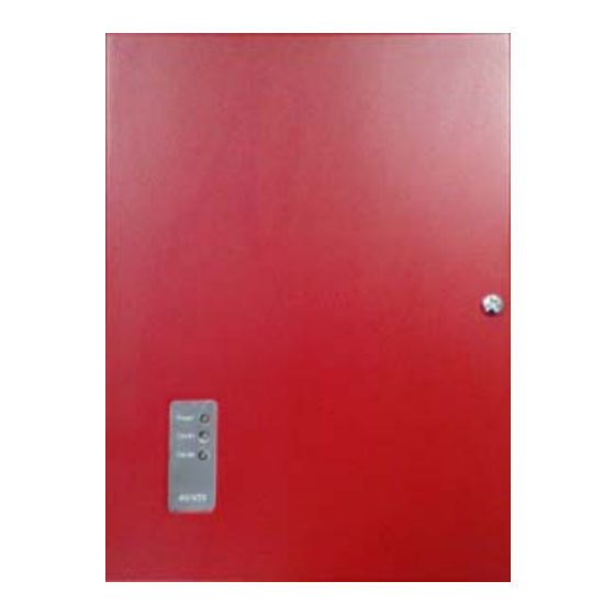
Introduction The Advanced AV-V70 is a universal audio converter that converts any ANSI/UL Listed, maximum 40 Watt, 25Vrms speaker circuit to a 40 Watt 70Vrms speaker circuit. The AV-V70 includes a 70Vrms Speaker Circuit Interface Card, an Audio Converter Transformer, an LED Indicator Card and an enclosure. Each AV-V70 enclosure is capable of supporting two (2) 70Vrms Speaker Circuit Interface Cards and Audio Converter Transformers. -
Page 4: General Installation Notes
General Installation Notes USE an anti-static wrist strap WARNING: Disconnect all sources of power whenever handling circuit cards. ATTENTION before installing or servicing the AV-V70. OBSERVE PRECAUTIONS FOR HANDLING ELECTROSTATIC SENSITIVE DEVICES STORE circuit cards in static DO NOT install/remove circuit cards or suppressive packaging. -
Page 5: 25Vrms "Host" Speaker Circuit Wiring
9" 4 1/2” 1 1/8" 11 7/8" 10 3/4" Grounding Screw 4 1/4” 3" 7 3/4” Figure 3 – AV-V70 Enclosure Dimensions and Mounting Note: Failure to ground the AV-V70 enclosure or to tighten screws associated with PCB boards will defeat the protection circuitry designed to protect the modules/cards from damage due to lightning and static electricity. -
Page 6: 24 Vdc Power Wiring
Figure 4 – 70Vrms Speaker Circuit Interface Card, “Host” Class B Speaker Circuit Wiring Figure 5 – 70Vrms Speaker Circuit Interface Card, “Host” Class A Speaker Circuit Wiring 24 VDC Power Wiring The 70Vrms Speaker Circuit Interface Card requires 24 VDC regulated and power-limited power from the “Host” fire alarm control panel or from an ANSI/UL Listed power supply. -
Page 7: 70Vrms Speaker Circuit Wiring
Figure 6 – 70Vrms Speaker Circuit Interface Card 24 VDC Wiring 70Vrms Speaker Circuit Wiring The 70Vrms Speaker Circuit Interface Card can be wired to the 70Vrms speakers either via Class A or Class B wiring. If wiring Class B, set 70Vrms speaker circuit output style wiring jumper to B, and wire terminals B+ and B- of the 70Vrms Speaker Circuit Interface Card to each speaker, terminating the wiring with a 100K end-of-line resistor [EOL] (see figure 7). -
Page 8: Prewired Audio Converter Transformer And Led Indicator Card
Figure 8 – 70Vrms Speaker Circuit Interface Card 70Vrms Class A Wiring Prewired Audio Converter Transformer and LED Indicator Card As previously indicated, the AV-V70 includes an installed 70Vrms Speaker Circuit Interface Card prewired to the Audio Converter Transformer and the LED Indicator Card. Wiring to the Audio Converter Transformer includes both the 25Vrms input wiring and the 70Vrms output wiring (see figure 9). -
Page 9: 70Vrms Speaker Circuit Interface Card And Audio Converter Transformer Expansion
Figure 10 – 70Vrms Speaker Circuit Interface Card Wiring to LED Indicator Card 70Vrms Speaker Circuit Interface Card and Audio Converter Transformer Expansion As previously indicated, the AV-V70 universal audio converter is capable of supporting two (2) 70Vrms Speaker Circuit Interface Cards and Audio Converter Transformers. Adding an additional 70Vrms Speaker Circuit Interface Card and Audio Converter Transformer requires acquiring and installing an AV-V70-KIT. - Page 10 LED Indicator Card, installed on the AV-V70 enclosure door, this is a keyed connection and can only be installed one way (see figure 11). Wire 24VDC regulated and power-limited power from the “Host” fire alarm control panel or from an ANSI/UL Listed power supply to terminals 0V and +24V of the newly installed 70Vrms Speaker Circuit Interface Card [0V = negative, +24V = positive].
-
Page 11: Module Specifications
Module Specifications AV–V70 Universal Audio Converter Specifications Operating Voltage 24VDC (wired from FACP 24VDC or a Listed power supply) Operating Current 60mA Trouble Relay Contact Rating 1A @ 30VDC Temperature (Indoor/Dry Environment) 32–120 F (0-49 Relative Humidity 93% Non Condensing (maximum) Dimension 12”H x 9”W x 3”D Weight... - Page 12 Doc Number: 682-044 AFS Revision: 100 South Street, Hopkinton, Massachusetts 01748 Tel: (508) 435-9995 Fax: (508) 435-9990 Email: usa@advancedco.com Web: www.advancedco.com www.advancedco.com...


Need help?
Do you have a question about the Axis AX AV-V70 and is the answer not in the manual?
Questions and answers