
Summary of Contents for Mikroe CODEGRIP UNIVERSAL
- Page 1 Time-saving embedded tools U N I V E R S A L U N I C O D E G R I P U S E R M A N U A L...
- Page 2 Thank you for choosing MIKROE! We present you the ultimate programmer & debugger over WiFi/USB solution for embedded development. Elegant on the surface, yet extremely powerful on the inside, we have designed it to inspire outstanding achievements. And now, it’s all yours.
-
Page 3: Table Of Contents
Ta b l e o f c o n t e n t s Introduction 4. CODEGRIP Suite overview 1. Installing CODEGRIP Suite 4.1 Menu section 2. CODEGRIP 4.2 Menu item section 2.1 USB connectivity 4.3 Shortcuts bar 2.2 WiFi connectivity 4.4 Status bar section 2.3 Target connector 5. -
Page 5: Introduction
programming of a huge number of microcontrollers becomes UNI CODEGRIP is a unified solution, designed to perform seamless and effortless, providing users with both the programming and debugging tasks on a range of different mobility and the complete control over the microcontroller microcontroller devices (MCUs) based on both the ARM®... -
Page 6: Installing Codegrip Suite
1. Installing CODEGRIP Suite The installation process is easy and straightforward. Download CODEGRIP Suite software application from the link www.mikroe.com/setup/codegrip and follow the steps below. Start the Select the installation destination folder Select the License components agreement to install U N I C O D E G R I P U S E R M A N U A L... - Page 7 Select the Start the start menu installation shortcuts process Installation Finish the progress installation process U N I C O D E G R I P U S E R M A N U A L...
-
Page 8: Codegrip
2. CODEGRIP The CODEGRIP device offers a set of unique and innovative functionalities, some of which have never been used before on a similar device. These functionalities include wireless programming and debugging, power monitoring, advanced debugging options with the SWO support, and more. The CODEGRIP device comes in two different types: as a stand-alone device and an integrated on-board module. -
Page 9: Usb Connectivity
To use the WiFi functionality, a separate registration code is required. It N O T E debugging the firmware in real time, programming it with a new firmware can be bought from the official Mikroe online store www.mikroe.com during exposure, having sensor responses collected and logged remotely... -
Page 10: Target Connector
2.3 Target connector The CODEGRIP device is equipped with the connector used to interface On the bottom of the CODEGRIP device there is the sticker which contains the device with the target MCU. The connector allows it to perform additional information. programming and debugging operations, to provide the power supply for ∫... - Page 11 TARGET CONNECTOR FOR ARM AND RISC-V TARGET CONNECTOR FOR AVR VCC-TGT SWDIO/TMS VCC-TGT ISP_MOSI/JTAG_TDI SWDCLK/TCK ISP_CLK/JTAG_CLK SWO/TDO ISP_MISO/PDI_DATA/UPDI_DATA/JTAG_TDO RESERVED RESERVED JTAG_TMS PROG MUX/GND TGT-RESET PROG MUX/GND RESET/PDI_CLK/DW_DATA RESERVED RESERVED RESERVED RESERVED RESERVED RESERVED RESERVED RESERVED RESERVED RESERVED...
- Page 12 TARGET CONNECTOR FOR PIC AND dsPIC TARGET CONNECTOR FOR PIC32 VCC-TGT RESERVED VCC-TGT ETJTAG_TMS ICSP_CLK EJTAG_CLK / PGEC ICSP_DATA EJTAG_TDO / PGED RESERVED RESERVED RESERVED EJTAG_TDI PROG MUX/GND PROG MUX/GND MCLR MCLR RESERVED RESERVED RESERVED RESERVED RESERVED RESERVED RESERVED RESERVED RESERVED RESERVED...
-
Page 13: Codegrip Adapters
2.4 CODEGRIP adapters Programming/debugging headers may vary across different hardware applications. To ensure compatibility with various header configurations there is a set of different adapters available as an additional purchase option. -
Page 15: Led Indicators
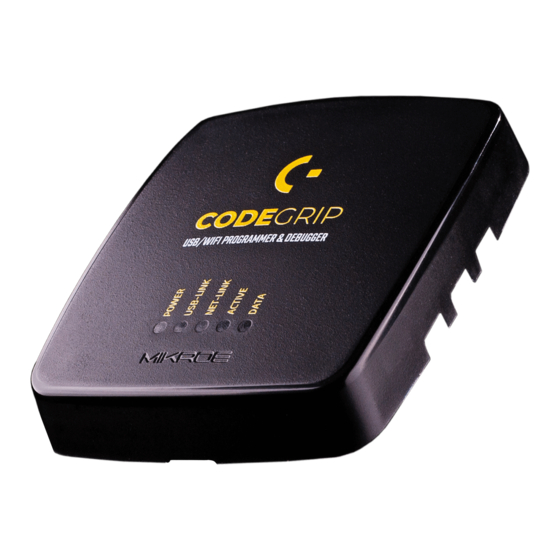
2.5 LED indicators There are five LED indicators on the CODEGRIP device, used to indicate different states of the device, providing visual feedback to the user. POWER Indicates the presence of the power USB-LINK supply Indicates that the connection has been established via USB NET-LINK Indicates that the... -
Page 16: Codegrip Link Structure
3. CODEGRIP link structure 3.2 Link states CODEGRIP Suite can detect multiple CODEGRIP devices. In addition, a single CODEGRIP device can be operated by multiple software applications. To avoid any ambiguity, CODEGRIP utilizes the concept of links. Each link has several different states recognized by the CODEGRIP Suite. CODEGRIP Suite uses a link to the specific CODEGRIP device, in order to send The link is Closed: the CODEGRIP device is not available over the commands and receive responses. -
Page 18: Codegrip Suite Overview
4. CODEGRIP Suite overview The graphical user interface (GUI) of CODEGRIP Suite is clear, intuitive, and easy to use, which ensures a fluid workflow. The main window is divided into several sections, which are used to display and organize all information, tools, and options in a consistent and comprehensible manner. -
Page 19: Menu Section
4.1 Menu section 4.3 Shortcuts bar As already mentioned, all Menu buttons are located in the Menu section The Shortcuts bar is another persistent section of the CODEGRIP of the CODEGRIP Suite GUI. By clicking a Menu button, one or more Menu Suite GUI, containing controls for the most commonly used commands. -
Page 20: Status Bar Section
4.4 Status bar section Link status indicator: provides visual feedback about the status of the link. The Status bar is located at the very bottom of the GUI and it is used to provide persistent visual feedback about the CODEGRIP link status. A set of When working with multiple devices, it is sometimes useful to have visual indication of the device which is currently linked with the CODEGRIP Suite. -
Page 21: Codegrip Suite Explained
5. CODEGRIP Suite explained As already mentioned, each Menu button contains one or more related Menu items, and each Menu item contains its own set of tools and options, displayed in a form of various GUI elements on the Menu item section. This chapter provides detailed information on these tools and options. - Page 22 5.1.1 Programming The displayed options may vary depending on the selected target. Below is the interface used to select and display the program file .bin or .hex file, ready to be uploaded to the target MCU or examined by using a set of options, accessible by clicking the FLASH button.
- Page 23 SOURCE programming protocol, speed and other parameters found in the TARGET/ Options Menu item. Before memory is written, the target MCU flash will be The name of the currently loaded .hex or .bin file is displayed in this field. erased. This file contains the program data that will be uploaded to the target MCU.
- Page 24 READ button Find READ button performs a reading of the target MCU flash memory content. This function is used to search for an occurrence of the value specified in The content of the memory is then available for the FLASH button related the textbox.
- Page 25 To simplify working with the SWO trace port, Mikroe has provided the SWO library with ready-made functions, which can drastically speed up the software development. The library is available for download from the Libstock at libstock.mikroe.com...
- Page 26 5.1.3 Options Set Filters This button opens a new window, which contains five checkboxes, used to manage the incoming SWO messages. There are three message categories, depending on the SWO port they are sent through: Info, Warning, and Error messages. When the specific checkbox is ticked, messages corresponding to that category will be displayed.
- Page 27 Vendor If Enabled, the MCU software execution will be halted after the connection to the target MCU is established. Options: a list of supported MCU vendors. The Vendor dropdown menu allows the MCU vendor to be selected. If All is If Disabled, the program will continue running on the target MCU freely, selected the vendor filtering will not be applied.
- Page 28 Target Browse window By clicking the browse button next to the MCU selection dropdown menu, the Target Browse window will pop up. The Target Browse window contains a vendor drop down menu and MCU textbox. Typing in this textbox will dynamically filter the MCU list, showing only the MCU names that contain the characters typed so far.
- Page 29 Dark or Light..it’s your choice!
-
Page 30: Codegrip
5.2 CODEGRIP The CODEGRIP Menu button contains Menu items related to the detection and setup of the CODEGRIP device. 5.2.1 Scanning The Scanning Menu item contains tools for detecting CODEGRIP devices. This Menu item also provides controls for link management. There are two tabs displayed in the Menu item section, Scan List tab and Options tab. - Page 31 WiFi LINK button This button is used to create or destroy the WiFi link. Note that the CODEGRIP device must be properly configured and discoverable over the WiFi network for this option to work (more information can be found in the Configuration Menu item description, in this chapter). SCAN DEVICES button This button will start the scanning process.
- Page 32 5.2.2 Configuration When Configuration Menu item is clicked, a set of four tabs will be displayed in the Menu item section Device General, WiFi General, WiFi Mode, and Licenses, each with its own set of options. On the bottom of the Menu item section, there are two buttons: RELOAD CONFIGURATION button will read back the configuration values from the CODEGRIP device, refreshing the content of CODEGRIP Suite.
- Page 33 The Available Licenses subsection displays all licenses currently available for purchase. The license activation process itself is explained in the in the chapter 5.2.3. Licenses can be purchased at the Mikroe store in the same way as any other item: For WiFi license, please visit www.mikroe.com/codegrip-wifi-license...
- Page 34 WiFi General tab This tab contains general WiFi information about the linked CODEGRIP device. Interface State Options: Enabled, Disabled The integrated WiFi module can be enabled or disabled by selecting an option from this dropdown menu. The Enabled option will enable the integrated WiFi module, allowing it to be used.
- Page 35 This dropdown menu allows to set up the encryption method for the WiFi network traffic. N O T E WiFi and SSL licenses are bought separately, from the MIKROE Once entered, the password for the specific CODEGRIP device is N O T E online store.
- Page 36 WiFi Mode tab This tab contains some specific WiFi settings for each of the two available modes of operation. There are two subsections labeled as Access Point Mode and Station Mode. WiFi settings are grouped into these subsections, according to the mode they are used for. Access Point Mode subsection SSID This is the wireless network identifier, up to 32 characters long.
- Page 37 Station Mode subsection Subnet mask All configuration settings related to the Station Mode are shown in this Network subnet mask can be set in this field. subsection When operated in the Station mode, the CODEGRIP device becomes the WiFi client. Gateway SSID This field is used to set the IP address of the default gateway device.
- Page 38 5.2.3 License License Menu item offers a set of options that are used to activate a license and enter user information, allowing personalization of the CODEGRIP device. When the License Menu item is clicked, the Menu item section displays two subsections. The subsection labeled as User information contains text boxes which allow some general user information to be entered, including a user name, email, company, and so on.
- Page 39 LICENSES button will be disabled. The text field containing an invalid permanently stored within the CODEGRIP device. value will display the invalid option/string in red letters. For WiFi license, please visit www.mikroe.com/codegrip-wifi-license For SSL security license, please visit www.mikroe.com/codegrip-ssl-license Registration Codes subsection In this subsection, there are buttons used to facilitate the licensing process.
-
Page 40: Power
5.3 POWER 5.3.1 Outputs When the Outputs Menu item is clicked, the Menu item section will be divided into two subsections: Controls and Measurements. The Controls subsection offers a set of options used to control power-related parameters, while the Measurements subsection offers visual feedback of the power-related parameters. -
Page 41: Options
5.4 OPTIONS 5.4.1 General The Menu item section is divided into two subsections, labeled as Target and Suite. Erase Type Options: Erase Chip, Erase only Necessary Sectors, Unlock and Erase Chip Erase Chip will erase the content of the target MCU flash memory. Erase only Necessary Sectors will only erase those sectors to which the data from the loaded .hex or .bin source file will be written. -
Page 42: Help
5.5 HELP HELP Menu button reveals two Menu items when clicked: About and Updates. These Menu items contain some general information about the CODEGRIP, along with the CODEGRIP Suite update and firmware update tools. 5.5.1 About By clicking on About Menu item, some general information that covers the current version of the release, the development team, and links to the site and email address will be displayed in the Menu item section. - Page 43 5.5.2 Updates This Menu item contains tools used to update the Suite itself, as well as the firmware of the CODEGRIP device. There are three tabs on the Menu item section when this Menu item is clicked: the Suite tab, the CODEGRIP tab, and the Power Module tab.
-
Page 44: Troubleshooting
Error Messages Troubleshooting Target is not detected (DETECT) Make sure that the selected MCU matches the MCU connected to the CODEGRIP device. Check that the selected interface is supported on the target MCU. Make sure that the program lines are correctly configured. ∫... - Page 45 D I S C L A I M E R All the products owned by MikroElektronika are protected by copyright law and international copyright treaty. Therefore, this manual is to be treated as any other copyright material. No part of this manual, including product and software described herein, must be reproduced, stored in a retrieval system, translated or transmitted in any form or by any means, without the prior written permission of MikroElektronika.
- Page 46 If you want to learn more about our products, please visit our website at www.mikroe.com If you are experiencing some problems with any of our products or just need additional information, please place your ticket at www.mikroe.com/support Time-saving embedded tools If you have any questions, comments or business proposals, do not hesitate to contact us at office@mikroe.com...
Need help?
Do you have a question about the CODEGRIP UNIVERSAL and is the answer not in the manual?
Questions and answers