Table of Contents
Advertisement
Quick Links
CRUISING 300 AND CRUISING 600
Installation and instruction manual
Version
Date
Contact
You have just purchased the most powerful hydrogenerator of its kind. Inspired by the requirements
of ocean racing yachts, designed to take into account the stresses experienced by monohulls, this
hydrogenerator will radically change your energy management at sea and become your main
source of power while sailing.
This product has been thoroughly inspected. The product comes with the WATT&SEA warranty
described in the "Warranty Terms" chapter of this installation guide. For traceability under the
warranty, please register the product on our website: www.wattandsea.com
HYDROGENERATOR
V5
03/2022
contact@wattandsea.com
Congratulations !
Designed & manufactured in France by:
WATT&SEA SARL
3 rue Jacques Cartier
17000 La Rochelle
France
www.wattandsea.com
35
Advertisement
Table of Contents

Summary of Contents for WATT&SEA CRUISING 300
- Page 1 HYDROGENERATOR CRUISING 300 AND CRUISING 600 Installation and instruction manual Version Date 03/2022 Contact contact@wattandsea.com Congratulations ! You have just purchased the most powerful hydrogenerator of its kind. Inspired by the requirements of ocean racing yachts, designed to take into account the stresses experienced by monohulls, this hydrogenerator will radically change your energy management at sea and become your main source of power while sailing.
-
Page 2: Table Of Contents
ONNECTING THE CONVERTER TO THE BATTERIES NTERPRETATION OF THE CONVERTER SING LUETOOTH INSTALLATION SUMMARY SPECIFICATIONS CRUISING 600 ECHNICAL SPECIFICATIONS OF THE MM AND CRUISING 300 ECHNICAL SPECIFICATIONS OF THE MM AND PERATING PRINCIPLES ERFORMANCE MAINTENANCE LIST OF SPARES 10. F.A.Q 11. WARRANTY... -
Page 3: Safety Precautions
1. SAFETY PRECAUTIONS While our primary concern in designing the hydrogenerator was your safety, certain precautions must nevertheless be taken when operating any mechanical or electrical equipment. Please keep the following safety factors in mind when installing and operating the hydrogenerator, and be aware at all times of the electrical and mechanical hazards inherent in operating the propeller. -
Page 4: Installation
Installation Please observe the following precautions during installation : • Remove the hydrogenerator from the water. • Keep safety in mind at all times ! Have someone help you throughout the duration of the installation. • Remember : the batteries should be connected last. Operation •... -
Page 5: Contents Of The Hydrogenerator Pack
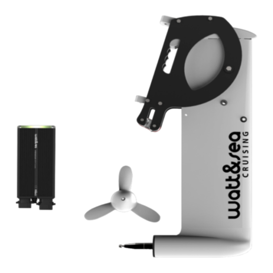
2. CONTENTS OF THE HYDROGENERATOR PACK Check the contents of your pack against the list below : - 1 HYDROGENERATOR with 5 metres of cable (H-300-03 or H-600-03) - 1 LIFTING BRACKET (K-03) - 1 THREE-BLADE (P-240-03) - 1 PROPELLER EXTRACTION KIT (EP-03) - 1 CONVERTOR (CV-03) with its bag of connectors : - 1 hydrogenerator connector - 1 solar connector... -
Page 6: Additional Equipment Required
3. ADDITIONAL EQUIPMENT REQUIRED • Three-phase cable, minimum 3 x 1.5 mm , for connecting the hydrogenerator to the converter (if length < 10m; if length >10m please use 2,5mm • Red and black 10 mm cable for connecting the batteries. •... -
Page 7: Mechanical Installation
4. MECHANICAL INSTALLATION Your hydrogenerator is shipped partially disassembled. Please read the instruction manual carefully before starting installation. Assembling the propeller • Slide the propeller onto the shaft. • Check that the stainless steel washer (3) has been pre-mounted at the end of the propeller. -
Page 8: Positioning The Hydrogenerator On The Transom
Positioning the hydrogenerator on the transom Correctly positioning the hydrogenerator is crucial for optimizing its performance. The following criteria must be respected during the installation : Immersion depth : • The hydrogenerator is supplied with a submerged aluminium leg measuring 610 mm (24 in) or 970 mm (38 in). - Page 9 Examples of installations with the shorter leg (610 mm / 24 in) : • Dual installation on a Pogo40 (© CN STRUCTURES) The hydrogenerators are placed parallel to the rudders but approximately 30 cm (12 in) to the inside to avoid their wakes. Installation on a catamaran (©...
-
Page 10: Installing The Bracket On The Transom
Installing the bracket on the transom Depending on your boat's transom, its structure might need to be reinforced to take the stress on the mountings. Phonic insulation also reduces vibrations. WARNING : Due to the size of the lever arm, the maximum theoretical stress on the bracket's fork mountings is estimated at around 300 kg. -
Page 11: Lifting System
Rigging the immersion/lifting system The hydrogenerator is supplied with a lifting bracket that functions in a similar way to the systems used on the rudders. It facilitates access to the propeller when the device is lifted, for the removal of seaweed for example. The lowering and lifting procedures are carried out using a hoist which is not included in the pack. - Page 12 The cleat integrated into the bracket is used to lock the lowering and lifting line. For permanent blocking in lower position, you can use the locking pin. Please take care in pull in a vertical way on the immersion and lifting lines to avoid the cleat from opening unexpectedly.
-
Page 13: Dismantling The Propeller
Dismantling the propeller To dismantle the propeller, you should use the M6 extractor screw (supplied with the hydrogenerator.) • Unscrew the M5 screw that holds the propeller at the end of the shaft. • In its place, insert the M6 screw and tighten it using the appropriate key. This will have the effect of effortlessly removing the propeller from its conical fitting. -
Page 14: Electrical Installation
5. ELECTRICAL INSTALLATION Recommendations for electrical connections : Please consult local/national safety rules before installation. All electric cables must be carefully insulated. For maximum protection, cover the cables with electrical cable sheaths. WARNING : CONNECTIONS MUST BE INSPECTED REGULARLY TO DETECT SIGNS OF CORROSION AND CLEANED WHEN NECESSARY. -
Page 15: Using A Solar Panel
not used / non utilisé BATT #1 POSITIVE POSITIF BATTERIE N °1 (female contact / contact femelle) HYDROGENERATOR CONNECTOR BATT #2 POSITIVE (female contact / contact femelle) Phases : RED, ORANGE, BROWN (Rouge, Orange, Marron) POSITIF BATTERIE N °2 (female contact / contact femelle) Not used : BLACK (Noir non utilisé... -
Page 16: Connecting The Converter To The Batteries
When the hydrogenerator and the solar panel generate power at the same time, priority is given to the hydrogenerator. As soon as this is no longer generating power (lifted, the boat is moored) the converter automatically takes into account the solar panel's charge. Connecting the converter to the batteries The converter must be placed as close as possible to the batteries in order to minimize losses due to cable length. - Page 17 sig. ORTANTE: Proteggere dalla polvere NOTE: Protect the plug-in connectors vement les valeurs données pour la ten- 'umidità i connettori. from humidity and dirt. ACHTUNG: Schützen sion nominale et pour l'intensité nominale. binder vor Feuchtigke mmergere in acqua i connettori. Le plus petit dénominateur commun est –...
-
Page 18: Sled S
Interpretation of the converter's LEDs - When the converter is not charging, the battery CHARGE voltage is indicated by a pulse of color which changes U BATT (V) Power(W) from green (12.8 V) to red (11.5 V). - When the converter is charging, the output power is 12,8/25,6 480+ indicated by a constant color which changes from... -
Page 19: Using Bluetooth
Using Bluetooth Since the end of 2019, Watt&Sea converters embed a Bluetooth chip (serial numbers above CV- 03-1630). The Watt&Sea application is available on Appstore and Google Play. It will allow you to track your hydrogenerator's production, make data records, and adjust charging settings. To install and use the application: •... -
Page 20: Installation Summary
6. INSTALLATION SUMMARY The following instructions set out the main steps in the hydrogenerator installation procedure. This is only a summary. Please refer to the appropriate sections of this manual for detailed instructions. Place the propeller onto the device. (See 4.1) Mechanically mount the hydrogenerator onto the transom. -
Page 21: Specifications
7. SPECIFICATIONS Technical specifications of the 970 mm and 610 mm CRUISING 600 w Hydrogenerator (H-600-03) : w Converter (CV-03): Nominal power: 600 W Nominal power: 600 W Nominal voltage: Three-phase, 40 V Absorption voltage: 14.3 V / 28.6 V Rated current: 9 A Floating voltage: 13.8 V / 27.6 V Weight: 8.2 kg / 7.4 kg... -
Page 22: 970 Mm And 610 Mm Cruising 300
Rated current: 9 A Rated current: 44 A / 22 A Weight: 7.1 kg / 6.3 kg Solar input: 50 V (mini 7,5V) / 14 A max Weight: 1.5 kg Dim.: 210 x 105 x 60 mm Dimensions of the CRUISING 300 hydrogenerator... -
Page 23: Operating Principles
Operating principles • The hydrogenerator : The hydrogenerator consists of a permanent magnet alternator producing a very low three-phase current (0-40 V). This alternator technology allows for very high output, but has the disadvantage of generating high voltages during overspeed. •... -
Page 24: Performance
Performance As detailed in section 4.2 concerning the installation of the hydrogenerator onto the transom, performance very much depends on position and the quality of water flow. The charts given below for the 600 and 300 models correspond with the measurements carried out on a motorboat with 200 mm, 240 mm and 280 mm propellers and a calibrated speedometer. - Page 25 Power output in relation to boat speed The average production values are given for information purposes only and may vary depending on the sea conditions and the quality of the installation.
-
Page 26: Maintenance
8. MAINTENANCE Originally designed for ocean racing, the hydrogenerator benefits from the latest technology where resistance and reliability are concerned. All metallic parts are made from either specially treated aluminium or A4 stainless steel. Watertightness is guaranteed using cutting-edge industrial gaskets that have a service life of several thousand hours and can easily support circumnavigation of the globe. -
Page 27: List Of Spares
9. LIST OF SPARES Exploded view of a hydrogenerator REFERENCE DESIGNATION G-600-03 Composite generator 600 W (no propeller) G-300-03 Composite generator 300 W (no propeller) CV-03 12-24 VCC auto-detected converter K-03 Lifting bracket with cam cleat P-200-03 Cruising three-blade propeller, 200 mm (7.9 in) P-240-03 Cruising three-blade propeller, 240 mm (9.5 in) P-280-03... -
Page 28: F.a.q
F.A.Q • What power can it produce ? The power generated depends on the size of the propeller and the speed of navigation. The table in section 7.4 gives the output power values in relation to speed for different propeller sizes. - Page 29 • The hydrogenerator does not charge as much as is shown in the charts, why is this ? The two most common causes of under-production are : An electrical connection problem : poorly connected/assembled power socket, damaged/corroded socket, cut or pinched cable. The hydrogenerator is positioned along the axis of an appendage (rudder, keel, etc.) which is disrupting the flow of water and affecting production.
-
Page 30: Warranty
WARRANTY Coverage and warranty period: Our products are designed for very specific conditions of use. It is the responsibility of our customers to ensure the appropriate use of our products. Our systems are covered by a two-year warranty against any manufacturing defect. The warranty period starts on the date of purchase of our products by the distributor. -
Page 31: Form For Requesting An After-Sales Service Return
FORM FOR REQUESTING AN AFTER-SALES SERVICE RETURN Owner Name: Phone no.: Address: E-mail: Country: Date of purchase of the hydrogenerator: Type of boat: Serial no. (see installation manual) - of the hydrogenerator: Type of assembly on the transom (if custom- - of the converter: made, please specify): Conditions of use (frequency/specific conditions having revealed the defect):... - Page 32 Retailer/Installer Name: Phone no.: Address: E-mail: Country: Date of purchase of the hydrogenerator: Has the defect been confirmed? Has the installation been carried out in Installer contact details: compliance with the instruction manual? Defective subassemblies to be replaced: Date: Signature: After Sales returns authorization no.:...