
Related Manuals for Polar Air SWC-EC Series


Summary of Contents for Polar Air SWC-EC Series
- Page 1 HIGHWALL SWC-EC Cooke Industries - Phone: +64 9 579 2185 Email: sales@cookeindustries.co.nz Web: www.cookeindustries.co.nz...
- Page 2 INVESTING IN QUALITY, RELIABILITY & PERFORMANCE ISO 9001 QUALITY World Leading Design and Technology Every product is manufactured to meet Equipped with the latest air-conditioning test rooms the stringent requirements of the and manufacturing technology, we produce over 50, internationally recognized ISO 9001 000 fan coil units each year, all conforming to the standard for quality assurance in design, highest international standards of quality and safety.
-
Page 3: Table Of Contents
Page 1 of 52 Table of Contents A. Technical Data ................................... 4 General Description..............................4 General Specifications ..............................5 2-pipe Systems ..............................5 Coil Data ..................................7 Dimensional Drawings ..............................7 Sound power data ............................... 9 Drain Pump and Installation Fixture (Optional) ......................13 B. - Page 4 Page 2 of 52 Drain Pump ................................28 Float Switch ................................28 Electric Heater Safety Switch ........................... 29 Low Temperature Protection of Indoor Coil in Winter....................29 Network Setup ................................ 30 Open Modbus Protocol ............................32 LED Display and Error Description ..........................36 E.
- Page 5 Page 3 of 52 Model Code Nomenclature Notation Description Hydronic High-Wall C Series Unit Size (See General Specification Section A for cooling and heating capacities.) V – 2-pipe Control type: I –Intelligent Control W – Flexible function Control EC Motor PG2021_SWC-V-ECM_02 Cooke Industries - Phone: +64 9 579 2185 Email: sales@cookeindustries.co.nz...
-
Page 6: Technical Data
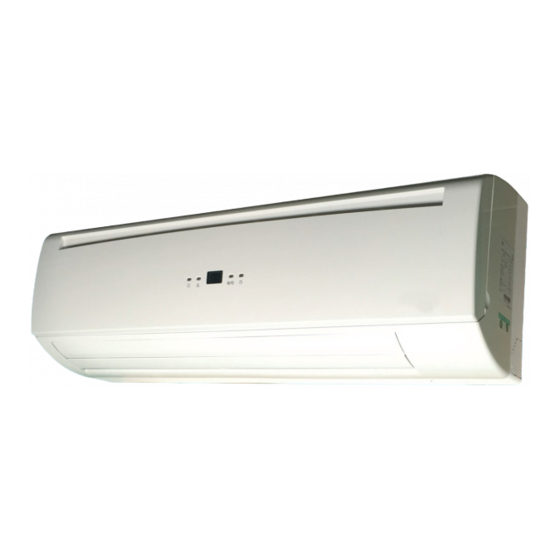
Page 4 of 52 General Description This High- Wall Unit is designed to meet and exceed demanding requirements for efficiency, quiet operation and appearance. The sleek profile and elegantly styled cabinet complement interior design theme, while the microprocessor assures accurate environmental control. Cabinet ~ the stylish cabinet is constructed of durable flame-resistant acrylonitrile-butadiene-styrene (ABS) plastic. -
Page 7: General Specifications
Page 5 of 52 General Specifications 2-pipe Systems SWC-ECM Hydronic High Wall Unit with EC Motor Product range: SWC-[Size]-V~-ECM Configuration 2-pipe Number Of Fan Blowers Single Power Supply (V/Ph/Hz) 220-240/1/50-60 Air Flow 1.82 2.10 3.01 Cooling Capacity 0.84 1.43 1.62 2.47 0.68 1.21... - Page 8 Page 6 of 52 Product range: SWC-ECM Hydronic High Wall with EC Motor SWC-[Size]-V~-ECM Configuration 2-pipe Number Of Fan Blowers Single Power Supply (V/Ph/Hz) 220-240/1/50-60 1080 1240 Air Flow 1080 3.71 4.81 5.33 5.93 Cooling Capacity 3.26 4.78 5.12 2.66 3.35 3.33 3.88...
-
Page 9: Coil Data
Page 7 of 52 Coil Data Tube Model Fin Height (mm.) Fin Length (mm.) Fins per Inch No. of Rows No. of Copper No. of Circuits Diameter (mm) SWC-04 SWC-06 SWC-12 SWC-15 19.5 SWC-18 SWC-20 SWC-24 SWC-30 Dimensional Drawings Dimensional drawing for SWC-04/06/12/15/18-ECM Unit Dimensions (mm) Model SWC-04/06/12/15/18... - Page 10 Page 8 of 52 Unit Dimensions (mm) Model SWC-20/24/30 1050 Unit Dimensions (mm) Model SWC-20/24/30 Unit Dimensions (mm) Model SWC-20/24/30 PG2021_SWC-V-ECM_02 Cooke Industries - Phone: +64 9 579 2185 Email: sales@cookeindustries.co.nz Web: www.cookeindustries.co.nz...
-
Page 11: Sound Power Data
Page 9 of 52 Sound power data Model SWC-04-ECM SWC-06-ECM SWC-12-ECM SWC-15-ECM SWC-18-ECM Speed H(700) M(600) L(500) H(930) M(700) L(600) H(930) M(700) L(600) H(1150) M(800) L(700) H(1300) M(1100) L(900) Sound Power 39.4 36.2 36.2 49.0 39.8 35.7 49.0 39.8 35.5 56.0 43.9 39.5... - Page 12 Page 10 of 52 Model SWC-04-18 Speed 100RPM 200RPM 300RPM 400RPM 500RPM 600RPM 700RPM 800RPM 900RPM 1000RPM 1100RPM 1200RPM 1300RPM 1400RPM Sound Power 32.2 32.3 32.8 33.1 35.2 35.6 39.1 43.5 47.4 50.6 53.7 56.2 59.3 61.3 dB(A) 20.0 Hz 18.0 19.7 14.7...
- Page 13 Page 11 of 52 Model SWC-20-ECM SWC-24-ECM SWC-30-ECM Speed H(1100) M(900) L(800) H(1200) M(1100) L(900) H(1350) M(1200) L(900) Sound Power dB(A) 53.8 49.2 44.6 57.3 53.8 49.4 60.3 56.9 49.4 20.0 Hz 21.2 18.3 22.8 22.5 17.0 17.0 20.8 19.9 17.0 25.0 Hz 18.7...
- Page 14 Page 12 of 52 Model SWC-20-24-30 Speed 100RPM 200RPM 300RPM 400RPM 500RPM 600RPM 700RPM 800RPM 900RPM 1000RPM 1100RPM 1200RPM 1300RPM 1400RPM Sound Power 32.7 32.3 33.0 34.6 35.2 36.9 40.2 45.1 48.6 51.8 54.3 56.9 59.2 61.3 dB(A) 20.0 Hz 19.4 19.5 20.8...
-
Page 15: Drain Pump And Installation Fixture (Optional)
Page 13 of 52 Drain Pump and Installation Fixture (Optional) Upon request, the metal bracket for fixing the drain pump and drain pump kits can be offered and preinstalled as optional. Please consult our sales representatives for these optional accessories. Sauermann condensate drain pump kits (optional) Metal bracket for fixing the drain pump on the unit (optional) PG2021_SWC-V-ECM_02... -
Page 16: Installation
Page 14 of 52 Safety Precautions • When installing, performing maintenance or servicing Polar Air fan coil units observe the precautions stated in this manual as well as those stated on the labels attached to the unit. • Ensure all local and national safety codes, laws, regulations, as well as general electrical and mechanical safety guidelines are followed for installation, maintenance and service. -
Page 17: Before Installation
Page 15 of 52 Before Installation Select the location for the high-wall unit with the following considerations: 1. The air inlet and outlet area should be clear without obstructions. The air should flow freely. 2. The high wall unit should be mounted on solid wall. 3. -
Page 18: Mounting Plate Dimensions
Page 16 of 52 Mounting Plate Dimensions SWC-04/06/12/15/18 –ECM SWC-20/24/30 –ECM (All dimensions shown in mm) PG2021_SWC-V-ECM_02 Cooke Industries - Phone: +64 9 579 2185 Email: sales@cookeindustries.co.nz Web: www.cookeindustries.co.nz... -
Page 19: Mounting Plate Installation
Page 17 of 52 Mounting Plate Installation 1. Select the structural position (e.g. a pillar or lintel) on the wall. 2. Then temporarily fasten the mounting plate on the wall with a steel nail. Mount the mounting plate horizontally as shown in the above figure or by means of gradiometer. -
Page 20: Hydronic Unit Installation
Page 18 of 52 Hydronic Unit Installation 1. Pass the piping through the hole in the wall and hook the indoor unit on the mounting plate by the upper hooks. 2. Move the body of the unit from side to side to verify if it is securely fixed. 3. -
Page 21: Pipe Connections With Valve
Page 19 of 52 Pipe Connections with Valve Pre-assembly Flexible hose Coil connector 1/2” gasket Valve body with actuator Complete Assembly PG2021_SWC-V-ECM_02 Cooke Industries - Phone: +64 9 579 2185 Email: sales@cookeindustries.co.nz Web: www.cookeindustries.co.nz... -
Page 22: Maintenance
Page 20 of 52 Opening and Closing of Lift-Up Grille Cover Open the grille cover by lifting from the bottom position indicated Close the grille cover by pressing down at the by the arrows. positions indicated by the arrows. Front Cover Assembly Removal 1. -
Page 23: Control Specifications: Intelligent Control (I Type)
Page 21 of 52 I/O Port Definitions Code Description Return air Sensor Return air temperature (Tr) Analogue Chilled water Sensor Water inlet temperature sensor (Ti1) Input Hot water Sensor Water outlet temperature sensor (Ti2) IR receiver X-DIS 1 Digital communication port to LED display/IR receiver board. Input Wired wall pad TTL1... -
Page 24: Wiring Diagrams
Page 22 of 52 Wiring Diagrams PG2021_SWC-V-ECM_02 Cooke Industries - Phone: +64 9 579 2185 Email: sales@cookeindustries.co.nz Web: www.cookeindustries.co.nz... -
Page 25: Control Logics For 2-Pipe System
Page 23 of 52 Control Logics For 2-Pipe System With Modulating Valve Configuration COOL MODE When unit is turned on in cooling mode. If Tr ≥ Ts + 1ºC (Modbus 300033 setting), MTV1 is turned on. AUX1 is closed. Fan is turned on at setting speed. DA2 is turned on at 10 VDC for 2 minutes, then check Ti1: When Ti1<=8ºC, DA2 output is based on water temperature difference (Ti1/Ti2) and Modbus parameter 300027 setting ... - Page 26 Page 24 of 52 When Tr > Ts+ 1ºC (Modbus 300033 setting), MTV1 and AUX2 is turned off. DA2 is at 0 VDC. fan is turned on at lowest speed. When unit is turned off, MTV1 and AUX2 is turned off. DA2 is at 0 VDC. Fan is turned off delaying 2 minutes. ...
- Page 27 Page 25 of 52 The unit is on or standby, PRO input is open or closed, the unit is kept original state. The unit is off, PRO input is closed for 30S, MTV1 is turned on, DA2 is open at double of minimum setting (Modbus 300027 setting). Fan ...
-
Page 28: 2-Pipe Control Logic -With 6-Way Modulating Valve Configuration
Page 26 of 52 2-pipe Control Logic -With 6-way modulating Valve Configuration COOL MODE When unit is turned on in cooling mode: If Tr ≥ Ts + 1ºC (Modbus 300033 setting), MTV1 is turned on. AUX1 is closed. Fan is turned on at setting speed. ... - Page 29 Page 27 of 52 If Ti1 sensor is damaged, fan runs at setting speed. When Tr > Ts+ 1ºC (Modbus 300033 setting), MTV2 and AUX2 is turned off. EH is turned off. DA2 is at 5VDC. fan is turned ...
-
Page 30: Sleep Mode
Page 28 of 52 Sleep Mode Louver For remote handset Whenever the indoor fan is running, the louver can swing or stop at the desired position. Louver angle: 0~100º, opens clockwise with widest angle at 100º. Swing angle: 35~100º, opens clockwise to 68º. Below are the 4 fixed positions which can be set from wireless LCD handset. Position Angle 35º... -
Page 31: Electric Heater Safety Switch
Page 29 of 52 Electric Heater Safety Switch Low Temperature Protection of Indoor Coil in Winter This is frost protection for when the unit is off to prevent water in the coil and room from freezing. If 2pipe unit is in Standby Mode If Tr ≦... -
Page 32: Network Setup
Page 30 of 52 Network Setup 1. Disconnect the communication plug from the control box 2. Communication plug A, B, A, B is printed on the main PCB. When you connect the wires, please ensure connection of A to A and B to B. 3. - Page 33 Page 31 of 52 First unit Middle unit Last unit iii. Wire connection check 1) After the wire connection is completed, please check that the wire colours correspond. 2) Check the wire contact by using a multimeter. contact contact contact contact contact contact...
-
Page 34: Open Modbus Protocol
Page 32 of 52 Open Modbus Protocol Transfer Mode: RTU BAUD Rate: 9600bps, 8 data bit, 1 stop bit, None parity bit The communications require a delay between reading an answer and sending the next command of 80 ms.. All temperature is equal to reading data*10 accuracy: 0.1 degree C. - Page 35 Page 33 of 52 Holding Register table: Description Address Type* Remark Mode setting 300000 Cooling mode = 01(H) Humidify mode = 02(H) Fan mode = 04(H) Heating mode = 08(H) Auto mode = 10(H) Fan speed setting 300001 Low speed = 04(H) Medium speed = 02(H) High speed = 01(H) Auto fan speed = 07(H)
- Page 36 Page 34 of 52 Setting temperature range 300032 0=setting temperature range is from 16~30 1=Setting temperature range is fixed. Cooling=24 C Heating=21 Temperature band setting 300033 Reserved 300034 Reserved 300035 Reserved 300036 Reserved 300037 Reserved 300038 Reserved 300039 Reserved 300040 Reserved 300041 Reserved...
- Page 37 Page 35 of 52 Input Register table: Description Address Type* Remark Tr temperature sensor 400000 Ti1 temperature sensor 400001 Ti2 temperature sensor 400002 Reserved 400003 Reserved 400004 Error code 400005 Bit0 = Room temperature sensor error Bit1 = Ti1 temperature sensor error Bit2 = Ti2 temperature sensor error Bit3 = Float switch error Bit4 = Indoor coil low temperature protection...
-
Page 38: Led Display And Error Description
Page 36 of 52 LED Display and Error Description Power / Operation LED light (both green) Unit on Power LED Off, Operation LED On Unit in standby Power LED On, Operation LED Off For all units - Green LED Error Description Blink LED display Reason... - Page 39 Page 37 of 52 Filter Switch (S6 Green LED blinks 7 Filter switch is 2. replace the new filter PCB) times, stops for 3s opened. Only for unit with 1. Change fan speed to high. Electric Heater Green LED blinks 8 failure times, stops for 3s EH safety switch is...
-
Page 40: Control Specification: Flexible Function Pcb - W Type Control
Page 38 of 52 Abbreviation: Ti1 = Chilled water coil temperature I/O Port Definitions Code 2-Pipe Analogue Input Chilled water Sensor Coil sensor (Ti1) 230VAC input signals from wired thermostat. Power input 230VAC input signals from wired thermostat. Power supply to the PCB and all the loads connected to the Phase voltage outputs. -
Page 41: Wiring Diagram
Page 39 of 52 Wiring diagram PG2021_SWC-V-ECM_02 Cooke Industries - Phone: +64 9 579 2185 Email: sales@cookeindustries.co.nz Web: www.cookeindustries.co.nz... -
Page 42: Onboard Configuration
Page 40 of 52 Onboard configuration There is 1 DIP switch set on the PCB: DIPB (8 positions) SW1: configured for different modulating signal SW2 – SW4: brushless DC fan motor configuration. SW5 – SW8: Reserved Code State Description PCB configured for 0~5VDC modulating signal input. -
Page 43: Control Logics
Page 41 of 52 Control Logics Power On Setting When any fan speed is selected, the unit is turned on or modulating signal is more than 2VDC. When all of the fan speed inputs (H/M/L) are off and modulating signal is less than 2VDC, the unit is turned off. Alarm Protection and Error Display If EC motor is failure, EH relay is turned OFF at once. -
Page 44: Users Interface
Page 42 of 52 Remote Control Handset Attention When unit with handset is the master unit, its settings are automatically sent to the slave units. Auto Cool-Heat operation will be applicable in 4- pipe system only. “Swing” function is not applicable. European version only uses degree C setting. -
Page 45: Wired Wall Pad Controller Operation Guide
Page 43 of 52 LED display PG2021_SWC-V-ECM_02 Cooke Industries - Phone: +64 9 579 2185 Email: sales@cookeindustries.co.nz Web: www.cookeindustries.co.nz... -
Page 46: Dimensions And Installation
Page 44 of 52 Code Legend Code Legend Code Legend Monday Auto Mode Unit address Tuesday Sleep mode Unit No. / Error code Wednesday Swing mode Weekly timer Thursday LED lock C-cooling Friday Setting Temperature H-heating Saturday Room Temperature Energy consumption Sunday RH (if need) Energy consumption cycle... -
Page 47: Operation Guide
Page 45 of 52 Use screwdriver to remove the screw on the bottom Operation guide On/OFF Press to turn on. Press it again to turn off. Button Mode button With wall pad on, press to select Cooling, Dehumidification, Heating, Ventilation or Auto sequentially.or Auto sequentially. Fan Speed Button Press... - Page 48 Page 46 of 52 Long press for 5 seconds then short press it twice to set Timer ON. Press to set day of week from Monday to Sunday. Press to change Timer ON time. Press to turn Timer ON on or off and S8 appears or disappears. Long press for 5 seconds then short press it 3 times to set Timer OFF time.
- Page 49 Page 47 of 52 S31/S32 displays “U014”, which is used to set unit address. 1~255, default: 1 S31/S32 displays “U015”,which is used to set unit ESP. 0~100%, default: 40% , S31/S32 displays “U016”, which is reserved. S31/S32 displays“U017”, which is used to set software. (please refer to different PCB) 0=2-pipe with valve 1=2-pipe without valve 2=4-pipe with std valve...
- Page 50 Page 48 of 52 S32 : E** blinks Error code Bit0 = Room temperature sensor error Bit1 = Ti1 temperature sensor error Bit2 = Ti2 temperature sensor error Bit3 = Float switch error Bit4 = Indoor coil low temperature protection Bit5 = Indoor coil overheat protection Bit6 =Filter switch Bit7 = Electrical heater...
-
Page 51: Error Codes
Page 49 of 52 Error codes Error Description Code Reason Remedy 1. Check if Tr plug is connected or not. Room sensor unplugged or Room temperature sensor error damaged. 2. Check if sensor’s resistance is correct or not. 1. Check if Ti1 plug is connected or not. Ti1 sensor unplugged or Indoor coil sensor 1 failure damaged. -
Page 52: Sensor Resistance R-T Conversion Table
Page 50 of 52 Resistance: R (25°C) = 10KΩ ± 1% Beta Constant: B (25/85) = 3977 ± 1% Temp. Rmax Rnor (k Rmin Temp. Rmax Rnor (k Rmin (deg. C) (k Ohms) Ohms) (k Ohms) (deg. C) (k Ohms) Ohms) (k Ohms) 186.3613... - Page 53 Page 51 of 52 Temp. Rmax Rnor Rmin Temp. Rmax Rnor Rmin (deg. C) (k Ohms) (k Ohms) (k Ohms) (deg. C) (k Ohms) (k Ohms) (k Ohms) 5.4018 5.3146 5.2283 1.4137 1.3722 1.3317 5.1907 5.1049 5.0199 1.3681 1.3275 1.2880 4.9890 4.9045 4.8210...
-
Page 54: Troubleshooting
Page 52 of 52 Symptoms Cause Remedy Check for presence of voltage No voltage Check fuse on board The fan coil does not start Mains switch in the “OFF position Place in the “ON” position Faulty room control Check the room control Faulty fan Check fan motor Filter clogged... - Page 55 Cooke Industries - Phone: +64 9 579 2185 Email: sales@cookeindustries.co.nz Web: www.cookeindustries.co.nz...
Need help?
Do you have a question about the SWC-EC Series and is the answer not in the manual?
Questions and answers