Table of Contents
Advertisement
Quick Links
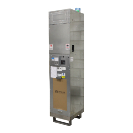
OMEGA VSHPe SERIES
Installation and Operation Manual (IOM)
Vertical Stacked
Water Source Heat Pumps
w/ Integrated ERV
MODEL: VSHPe (SE), VSHPe-G (HE)
FAN CABINET DEV. F
CHASSIS DEV.F, DEV. G
CONTROL BOARD: V3
DOCUMENT RELEASE: OMEGA-VSHPe.F-IOM-2205
Supersedes document OMEGA-VSHPe.F-IOM-2108
Revision Notes:
-Updated V3 Control Board (BLU)
-Maintenance Schedule Update
-Chassis Storage & Inspection
Advertisement
Table of Contents

Related Manuals for Omega VSHPe Series


Summary of Contents for Omega VSHPe Series
- Page 1 OMEGA VSHPe SERIES Installation and Operation Manual (IOM) Vertical Stacked Water Source Heat Pumps w/ Integrated ERV MODEL: VSHPe (SE), VSHPe-G (HE) FAN CABINET DEV. F CHASSIS DEV.F, DEV. G CONTROL BOARD: V3 DOCUMENT RELEASE: OMEGA-VSHPe.F-IOM-2205 Supersedes document OMEGA-VSHPe.F-IOM-2108 Revision Notes:...
-
Page 2: Table Of Contents
OMEGA-VSHPe.F-IOM-2205 TABLE OF CONTENTS 1. General Information, Warnings and Disclaimer ..............1 2. Cabinet Dimensions ....................... 2 3. General Unit Information ......................5 4. Inspection & Storage ......................5 Inspection of Unit ......................5 Storage ......................... 6 5. Cabinet & Riser Installation ....................6 For Shipped Loose Riser Shut-Off Valves .............. -
Page 3: General Information, Warnings And Disclaimer
OMEGA-VSHPe.F-IOM-2205 IMPORTANT READ THE FOLLOWING MANUAL PRIOR TO INSTALLATION, OPERATION and SER- VICING THIS UNIT. 1. GENERAL INFORMATION & WARNINGS SAFETY SYMBOLS – Warnings, Cautions & Notices There are three advisory symbols used in this document to alert the reader: Warning: Indicates a potentially dangerous situation which could result in death or serious injury. -
Page 4: Cabinet Dimensions
OMEGA-VSHPe.F-IOM-2205 2. CABINET DIMENSIONS VSHPe Cabinet Dimensions VSHPe Supply Discharge Opening ("W" X "H") Dimensions (in) Capacity Cabinet inches Model (Tons) Size Front Back Right/Left VSHPe 030 14 x 8 8 x 14 10 x 12 12 x 12 VSHPe 040... - Page 5 OMEGA-VSHPe.F-IOM-2205 VSHPe Cabinet and Chassis Weights Cabinet Chassis Model Cabinet (lbs) (lbs) VSHPe 030 VSHPe 040 VSHPe 050 VSHPe 060 VSHPe 080 VSHPe 100 VSHPe 120 Notes: Temporary riser supports provided (Contractor to remove and install permanent riser clamps fastening risers to the building structure).
- Page 6 OMEGA-VSHPe.F-IOM-2205 Supply, return and condensate riser field “knockouts”. Field “knockout” supply air openings (Front/Back/Side/Top) with 1-1/2” duct flange. ERV Ports—Bathroom Exhaust, Exhaust Air, Outside Air. Removable ERV core. Heat pump chassis. Chassis service cover panel. 1” air filter. Acoustic return air (R/A) panel for chassis, blower and electrical compartments.
-
Page 7: General Unit Information
OMEGA-VSHPe.F-IOM-2205 3. GENERAL UNIT INFORMATION cessing and servicing the ERV core, sensors and fans. The upper panel comes as either a blank panel or with a BLOWER & MOTOR supply grille. Removal of this panel allows access to The unit comes with a blower and motor assembly that outdoor air (OA) actuator. -
Page 8: Cabinet & Riser Installation
OMEGA-VSHPe.F-IOM-2205 rior insulation becoming wet and cause the growth FOR SHIPPED LOOSE RISER SHUT-OFF VALVES of mold which is known to cause odors and serious Visually inspect riser stub-outs and shut-off indoor air quality problems and health issues. valves for debris or damage. -
Page 9: Riser Loop
OMEGA-VSHPe.F-IOM-2205 8. Secure risers to building structure as per engineer- Chassis installation is permitted once the riser system is ing design specifications. Do not allow the risers to be thoroughly flushed, cleaned, and water loop is chemical- supported by the cabinets. Field supplied riser compen-... -
Page 10: Chassis Installation
OMEGA-VSHPe.F-IOM-2205 6. CHASSIS INSTALLATION 2) Use back-up wrench located at the front of the valve or secure to the middle of the valve Do not apply plumbers putty, pipe dope or body. Tighten a further 1/6 turn. Approx. 20FT/ sealing tape to NPSM fittings. -
Page 11: Unit Start-Up
OMEGA-VSHPe.F-IOM-2205 7. UNIT START-UP CHASSIS INSTALL Leave cardboard shipping cover on the air coil cov- Ensure the building fluid loop system has been cleaned, er in place. Check chassis nameplate to verify flushed, re-filled, chemically treated and commissioned chassis model matches cabinet model for compati- by the water treatment company. -
Page 12: Initial Start-Up
OMEGA-VSHPe.F-IOM-2205 ___All cutting, sanding, drywalling, patching work is complete. ___Unit blower spins freely. ___Thermostat is in the OFF position. ___Room temperature is above 60 INITIAL UNIT START-UP Close disconnect switch. Set thermostat to a high setting (above current room temperature), set system to COOL with fan on AU- TO. -
Page 13: Controls
OMEGA-VSHPe.F-IOM-2205 8. CONTROLS “Y” Terminal Closed (24V) = call for compressor Heating: “O/B” (0V) = Reversing Valve De-Energized MICROPROCESSOR CONTROLLER Cooling: “O/B” (24V) = Reversing Valve Energized DIP Switch Settings (BLU Board Only) Controller DIP switch contains 10 switches for setting up thermostat, Fan, and system settings. -
Page 14: Single/Manual Fan Mode Operation
OMEGA-VSHPe.F-IOM-2205 ultra low fan speed air circulation. (Optional) Entering Water Temperature (EWT) is • greater than 115oF Whisper Mode (Optional) Leaving Water Temperature (LWT) great- • Whisper mode is factory enabled and runs main blower er than 127oF fan at pre-determined low fan speed for continuous air circulation. -
Page 15: Erv Controls & Operation
OMEGA-VSHPe.F-IOM-2205 ERV CONTROLS & OPERATION Airflow Balancing—EA Fan Speed Adjustment ERV Control Board Balancing of the ERV unit between the OA and EA flows ensure maximum efficiency. The exhaust air fans should The ERV control board is powered by a 24VDC switch- be calibrated on site during start-up and commissioning ing power supply mounted in the electrical box. -
Page 16: Web Based Access
OMEGA-VSHPe.F-IOM-2205 This mode is disabled during the recycled air defrost mode. ERV FAN SETTINGS ERV Fan Setting The ERV fans are factory set to default position. It is recommended to perform an air balance to determine required fan speeds - Low and High. The potentiometers located on the ERV board controls the Low and High fan speeds. -
Page 17: Troubleshooting
(RJ45) on controller board. WEB PAGE ACCESS The Omega controller features a webpage configuration and troubleshooting tool. Unit status and diagnostics temperature (Supply Air, Entering Water, Leaving Water 3. On laptop access “Network and Sharing Center“... - Page 18 OMEGA-VSHPe.F-IOM-2205 7. Open up your internet browser (i.e. Explorer, Google Chrome) type following address 192.168.0.99. 8. The home page will load for the controller software. Below is a screen shot of the interface (version 5.4 soft- ware is shown). 6. With Internet Protocol Version 4 (TCP/IPv4) window open click on “Use the Following IP Address”...
- Page 19 OMEGA-VSHPe.F-IOM-2205 9. An event log feature called Log Dump allows for re- Y = call from thermostat to Y terminal cording unit operation information during faults or at start O/B = call from thermostat to O/B terminal -up as a troubleshooting aid. For example in the figure below the first line item indicates “Y”...
-
Page 20: Maintenance Guide
OMEGA-VSHPe.F-IOM-2205 10. MAINTENANCE GUIDE air coil may occur resulting in possible refrigerant leaks. Proper unit maintenance will result in optimal unit perfor- ANNUAL MAINTENANCE mance and prevent potentially costly repairs or property damage. Turn unit disconnect switch to off and turn unit... - Page 21 OMEGA-VSHPe.F-IOM-2205 Troubleshooting Guide Time To Likelyhood to Problem Mode Possible Cause(s) Correction Method Trip occur Heating/Cooling Main power off Check unit circuit breaker. Blown transformer / Blown 3 Amp fuse pops usually when there is a short to ground. Check thermostat wiring, control wiring,...
- Page 22 OMEGA-VSHPe.F-IOM-2205 Troubleshooting Guide : Chassis Low Voltage Controls Troubleshooting Low Voltage Chassis Controls Troubleshoot chassis low voltage using the low voltage chassis harness without the need to pull out chassis or re- move chassis top cover. Check resistance readings using a multi-meter probe to confirm continuity across: safeties (HPS, LPS), sensors (EWT, LWT, RST) and valves (ASOV, REV).
- Page 23 OMEGA-VSHPe.F-IOM-2205 Microprocessor LED Code Guide LED table applicable to Version 3 Board Description LED Code Alarm Description Red = Solid High pressure alarm. Hard Lock-Out. 3 Trips High Pressure Red = Blinking High pressure alarm. Soft Lock-Out Red = Solid Low pressure alarm.
- Page 24 OMEGA-VSHPe.F-IOM-2205 Riser Handing Configurations = Supply Riser = Condensate Riser = Return Riser Notes: As viewed from top, risers can be order in either SR configuration (supply, condensate, return) or RS (return, condensate, supply). Risers can be ordered from factory with 3 inch deep swage.
- Page 25 Offset indicates where the top of riser will be located relative to top of cabinet. A Base Datum indicates where bottom of riser will be located relative to base of cabinet. Upon request Omega will provide 3 inch deep swage on risers of same pipe size (optional for all risers) for connection to units on the floor below. ...
- Page 26 OMEGA-VSHPe.F-IOM-2205 Hose Kit Sizes Isolation Valve Notes: Hose Kit Model Standard NPSM sweat connected isolation valves are provided Size (in) Length (in) for Factory or Field Supplied Copper Risers. VSHPe 030 Optional Female NPT valves are for Field Supplied Risers only.
- Page 27 OMEGA-VSHPe.F-IOM-2205 Acoustic ERV RA Panel Dimensional Drawing Acoustic ERV RA Panel Sizes Acoustic RA Panel Dimensions Cabinet (inches) Model Size VSHPe 030 VSHPe 040 19 5/8 VSHPe 050 VSHPe 060 VSHPe 080 23 5/8 VSHPe 100 VSHPe 120 NOTES: ...
- Page 28 OMEGA-VSHPe.F-IOM-2205 Acoustic Return Air Panel Baseboard Cabinet Base 1.25" Flooring Concrete Slab Acoustic Panel Cabinet Base Height Calculation Acoustic ERV Panel Cabinet Base Height Calculation: Example: Baseboard - Base Height = Baseboard Height + Finish Floor Height* Baseboard Height* Cabinet Base Height = Gap (recommend min 0.5”) between baseboard and...
- Page 29 OMEGA-VSHPe.F-IOM-2205 Optional Supply Grille Removable core with door Notes: Perimeter Panel shown above with Optional Supply Grille. Panel is lined with acoustic insulation for enhanced sound attenuation. Return air panel supplied in standard powder coat appliance white finish.
- Page 30 OMEGA-VSHPe.F-IOM-2205 RA Panel Furring Details - Plan View Standard 1-Inch Filter Bracket Notes: Return air panel should be centered in front of the unit return air opening. Optionally, insulate the drywall enclosure with plenum rated acoustical insulation for additional sound attenuation.
- Page 31 OMEGA-VSHPe.F-IOM-2205 RA Panel Furring Details - Stud Furring Typ. 2x2 Closet Framing Notes: Return air panel should be centered in front of the unit return air opening. Optionally, insulate the drywall enclosure with plenum rated acoustical insulation for additional sound attenuation.
- Page 32 OMEGA-VSHPe.F-IOM-2205 Acoustic RA Panel Furring Sizes Cabinet Rough-In (in) Cabinet Dimensions (in) Model Size "X" "Y" VSHPe 030 VSHPe 040 21 1/2 20 1/8 78 1/2 VSHPe 050 Field Gasket Supply Grille VSHPe 060 Throat VSHPe 080 25 1/2 24 1/8...
- Page 33 OMEGA-VSHPe.F-IOM-2205 VHSPe Electrical Schematic—ECM Fan...
- Page 34 OMEGA-VSHPe.F-IOM-2205 Power Cable Entrance Low Voltage Notch For Control Wire Optional Front Entrance Low Voltage Control Wire Entrance Factory supplied 6- wire thermostat cable shown. Whisper Mode standard on G1 G2 Y O/B C VSHPe units. Jumper between R and G1...
- Page 35 OMEGA-VSHPe.F-IOM-2205 ECM Fan Data External Static Pressure (in w.g.) Unit EC Motor Minimum Rated 0.05 0.15 0.25 0.35 0.45 0.55 Size Speed SCFM SCFM SCFM SCFM SCFM SCFM SCFM SCFM SCFM SCFM SCFM SCFM SCFM SCFM SCFM WHISPER* MODE HIGH...
-
Page 36: Vshpe Unit Start-Up Sheet
Compressor Amp: ________ Compressor Amp: ________ Fan Amp: ________ Fan Amp: ________ Run Time For Test: ________ Run Time For Test: ________ Omega has a policy of continuous product improvement and reserves the right to change design and specifications without notice. - Page 37 ERV Air Balance Check: ____ Yes/No ERV Bathroom Timer On: ERV Bathroom Timer Wired: ____Yes/No ERV Fan Speed Ramps to High: ___ Yes/No Omega has a policy of continuous product improvement and reserves the right to change design and specifications without notice.
- Page 38 __________________________________________________________________________________________________________________ __________________________________________________________________________________________________________________ __________________________________________________________________________________________________________________ __________________________________________________________________________________________________________________ __________________________________________________________________________________________________________________ __________________________________________________________________________________________________________________ __________________________________________________________________________________________________________________ __________________________________________________________________________________________________________________ __________________________________________________________________________________________________________________ __________________________________________________________________________________________________________________ __________________________________________________________________________________________________________________ __________________________________________________________________________________________________________________ __________________________________________________________________________________________________________________ __________________________________________________________________________________________________________________ __________________________________________________________________________________________________________________ __________________________________________________________________________________________________________________ __________________________________________________________________________________________________________________ __________________________________________________________________________________________________________________ __________________________________________________________________________________________________________________ __________________________________________________________________________________________________________________ __________________________________________________________________________________________________________________ Omega has a policy of continuous product improvement and reserves the right to change design and specifications without notice.
Need help?
Do you have a question about the VSHPe Series and is the answer not in the manual?
Questions and answers