Table of Contents
Advertisement
Quick Links
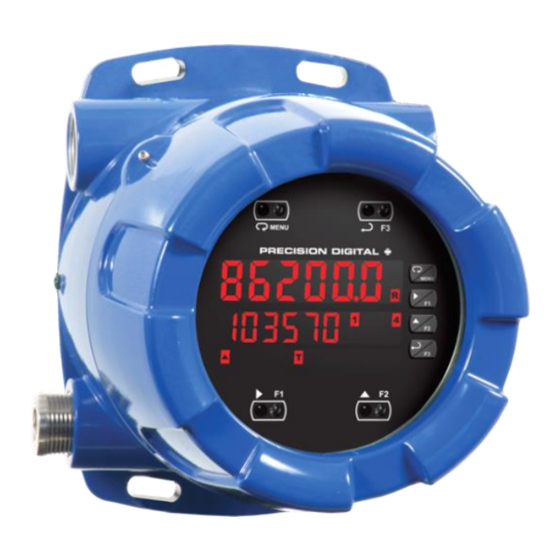
PD8-6200 Explosion-Proof Analog Input Flow Rate/Totalizer
Instruction Manual
•
Fully-Approved Explosion-Proof Analog Input Flow Rate/Totalizers
•
0-20 mA, 4-20 mA, 0-5 V, 1-5 V, and ±10 V Inputs with ±0.03% Accuracy
•
Dual-Line 6-Digit Display, 0.6" (15 mm) & 0.46" (12 mm)
•
SafeTouch Through-Glass Button Programming
•
Display Mountable at 0°, 90°, 180°, & 270°
•
Isolated 24 VDC @ 25 mA Transmitter Power Supply
•
Easy Field Scaling in Engineering Units without Applying an Input
•
4 Relays with Interlocking Capability + Isolated 4-20 mA Output Option
•
Free PC-Based, On-Board, MeterView Pro USB Programming Software
•
SunBright Display Standard Feature; Great for Outdoor Applications
•
Display Rate & Total at the Same Time
•
Rate in Units per Second, Minute, Hour, or Day
•
Total, Grand Total or Non-Resettable Grand Total
•
Front Panel or Remote Total Reset
•
Password Protection for Total Reset
•
Total Stored in Non-Volatile Memory
•
Assign Any Relay for Rate or Total
•
4-20 mA Output for Rate or Total
•
Display Open Channel Flow with Programmable Exponent Feature
•
32-Point Linearization & Square Root Extraction
•
Operating Temperature Range: -40 to 60°C (-40 to 140°F)
•
FM Approved as Explosion-Proof / Dust-Ignition-Proof / Flame-Proof
•
CSA Certified as Explosion-Proof / Dust-Ignition-Proof / Flame-Proof
•
ATEX and IECEx Certified as Flame-Proof
•
Input Power Options: 85-265 VAC / 90-265 VDC or 12-24 VDC / 12-24 VAC
•
Programmable Display, Function Keys & Digital Inputs
•
Flanges for Wall or Pipe Mounting
•
Explosion-Proof, IP68, NEMA 4X Die-Cast Aluminum Enclosure
•
On-Board RS-485 Serial Communications
•
®
Modbus
RTU Communication Protocol Standard
•
Password Protection
•
Four 3/4" NPT Threaded Conduit Openings (Two Plugs Installed)
•
Pipe Mounting Kits
•
Stainless Steel Tag Available
•
3-Year Warranty
PRECISION DIGITAL CORPORATION
233 South Street • Hopkinton MA 01748 USA
Tel (800) 343-1001 • Fax (508) 655-8990
www.predig.com
MeterView Pro
USB Install
Advertisement
Table of Contents

Related Manuals for Protex PD8-6200

Summary of Contents for Protex PD8-6200
- Page 1 PD8-6200 Explosion-Proof Analog Input Flow Rate/Totalizer Instruction Manual MeterView Pro USB Install • Fully-Approved Explosion-Proof Analog Input Flow Rate/Totalizers • 0-20 mA, 4-20 mA, 0-5 V, 1-5 V, and ±10 V Inputs with ±0.03% Accuracy • Dual-Line 6-Digit Display, 0.6" (15 mm) & 0.46" (12 mm) •...
- Page 3 Precision Digital The easiest and quickest way to program your Corporation shall not be held liable for damages ProtEX-MAX meter is to use the FREE MeterView Pro resulting from such improper use. programming software. This software is loaded into •...
-
Page 4: Table Of Contents
PD8-6200 Explosion-Proof Analog Input Flow Rate/Totalizer Instruction Manual Table of Contents Introduction ......................7 Ordering Information ..................7 Key Features ....................... 9 Specifications ....................17 General ......................17 Process Inputs ..................... 18 Rate/Totalizer ....................18 Relays ......................19 USB Connection ................... 19 Isolated 4-20 mA Transmitter Output ............ - Page 5 PD8-6200 Explosion-Proof Analog Input Flow Rate/Totalizer Instruction Manual Setting the Relay Operation (relay) ............41 Relay Assignment (Assign) ............... 41 Setting the Relay Action ................41 Programming Set and Reset Points ............42 Setting Fail-Safe Operation ................ 42 Programming Time Delay ................42 Relay Action for Loss of 4-20 mA Input (Loop Break) ........
- Page 6 PD8-6200 Explosion-Proof Analog Input Flow Rate/Totalizer Instruction Manual Table of Figures Figure 1. Enclosure Dimensions – Front View ..........23 Figure 2. Enclosure Dimensions – Side Cross Section View ....... 23 Figure 3. Transmitter Supply Voltage Selection ..........26 Figure 4. Integrated P Required Connections ........
-
Page 7: Introduction
PD8-6000 Process Meter To make it possible to program and operate the ProtEX-MAX in a hazardous area, the programming The PD8-6200 is essentially a PD8-6000 process buttons that are located behind the glass window can meter with flow totalization capability. The flow... - Page 8 (ProtEX-MAX) process meter using MeterView Pro software. predig.com/videos/4-20_mA_Connections Use ProtEX-MAX for Pump Control Learn how to use the ProVu (ProtEX-MAX) meter as an explosion-proof pump controller. See how the four relays can be used to alternate two pumps and provide high and low alarms.
-
Page 9: Key Features
Connections for PD8-6200-6H7 & PD8-6200-7H7 The Only Explosion-Proof Flow Rate/Totalizer You Will Ever Need The ProtEX-MAX PD8-6200 explosion-proof flow The first thing you notice about the PD8-6200 is its rate/totalizers are specifically designed for displaying modern looking, rugged, die-cast aluminum housing flow rate and total from flowmeters with analog outputs. - Page 10 532,831,470 by toggling between a display of “oF 532” and “831470”. ProtEX-MAX can be powered from the USB port, so no need to apply external power while programming Notice the (T with arrow ▲ symbol) is lit up indicating your meter.
- Page 11 The 4-20 mA output can be assigned to the rate or total. Display Rate & Total at Same Time One of the most useful features of the ProtEX-MAX Total Stored in Non-Volatile Memory flow rate/totalizers is their ability to display both flow Total and Grand Total values, and all programmed rate and total at the same time.
- Page 12 Total Reset via F4 Terminal and display open channel flow rate and total in most The PD8-6200 includes a digital input (referred to as weirs and flumes and take periodic samples. All the user the F4 terminal) located on the back of the electronics...
- Page 13 Flexible Mounting & Wiring Rugged, Heavy-Duty Enclosure The ProtEX-MAX features four ¾" NPT threaded The ProtEX-MAX is housed in a rugged NEMA 4X, 7, conduit openings so that wiring can be routed to the & 9, IP68 die-cast aluminum enclosure, designed to most convenient conduit connection(s).
- Page 14 Hazardous Area Approvals need it. The ProtEX-MAX's approvals allow it to be used in hazardous areas around the world. These include: FM Approved as Explosion-Proof / Dust-Ignition-Proof / Flame-Proof, CSA Certified as Explosion-Proof / Dust-Ignition-Proof, and ATEX and IECEx Certified as Flame-Proof.
- Page 15 Transmitter Power Supplies Meter Powers Transmitter One of the most useful standard features of the PD8-6200 is its built-in isolated, 24 V @ 25 mA power supply to power the transmitter. This feature saves money by eliminating an external power supply and also simplifies wiring by reducing the number of devices in the loop.
- Page 16 PD8-6200 Explosion-Proof Analog Input Flow Rate/Totalizer Instruction Manual Useful Tools PD9501 Multi-Function Calibrator This PD9501 Multi-Function Calibrator has a variety of signal measurement and output functions, including voltage, current, thermocouple, and RTD. PD9502 Low-Cost Signal Generator PD9502 is a low-cost, compact, simple to use 4-20 mA or 0-10 VDC signal generator.
-
Page 17: Specifications
PD8-6200 Explosion-Proof Analog Input Flow Rate/Totalizer Instruction Manual Specifications Non-Volatile Total and Grand Total values, and all Memory programmed settings are stored in non-volatile memory for a minimum of ten Except where noted all specifications apply to years if power is lost. -
Page 18: Process Inputs
PD8-6200 Explosion-Proof Analog Input Flow Rate/Totalizer Instruction Manual Process Inputs Rate/Totalizer Inputs Field selectable: 0-20 mA, 4-20 mA Rate Display -99999 to 999999, lead zero blanking. 10 V (0-5 V, 1-5 V, 0-10 V) “R” LED illuminates while displaying rate... -
Page 19: Relays
PD8-6200 Explosion-Proof Analog Input Flow Rate/Totalizer Instruction Manual Relays Isolated 4-20 mA Transmitter Output Rating 4 SPDT (Form C) internal and rated 3 A @ 30 VDC and 125/250 VAC resistive Output Rate/process, total, grand total, max, min, load; 1/14 HP (≈ 50 W) @ 125/250 VAC for... -
Page 20: Rs-485 Serial Communications
Connect normally open push buttons Turn Around Less than 2 ms (fixed) across +5 V & DI 1-4. Delay Note: Refer to the ProtEX-MAX Modbus Register Tables located at www.predig.com for details. • DO NOT use +5 V terminal to power external devices. -
Page 21: Compliance Information
PD8-6200 Explosion-Proof Analog Input Flow Rate/Totalizer Instruction Manual Compliance Information Product Ratings and Approvals Enclosure: Type 4X; IP66 Electromagnetic Compatibility Class I, Division 1, Groups B, C, D Class II, Division 1, Groups E, F, G Emissions EN 55022 Class III, Division 1, T5/T6... -
Page 22: Eu Declaration Of Conformity
PD8-6200 Explosion-Proof Analog Input Flow Rate/Totalizer Instruction Manual EU Declaration of Pre-Installed Conduit Plugs Conformity The ProtEX-MAX is supplied with two pre-installed conduit plugs for installations that do not require the EU Declaration of Conformity is available in the use of all four conduit entries. The conduit/stopping... -
Page 23: Mounting
PD8-6200 Explosion-Proof Analog Input Flow Rate/Totalizer Instruction Manual Wall Mounting Instructions Mounting The meter can be mounted to any wall or flat surface The ProtEX-MAX has four slotted mounting flanges using the four provided mounting holes located in the that may be used for pipe mounting or wall mounting. - Page 24 PD8-6200 Explosion-Proof Analog Input Flow Rate/Totalizer Instruction Manual Pipe Mounting Instructions Vertical Pipe Mounting Horizontal Pipe Mounting The meter can also be mounted to a pipe using an optional U-Bolt kit. This kit includes two U-bolts, the necessary hardware, and is available in zinc plated steel (PDA6848) and 316 stainless steel (PDA6848-SS).
-
Page 25: Installation Overview
“Yes.” MeterView Pro Software The easiest and quickest way to program your ProtEX-MAX meter is to use the FREE MeterView Pro programming software. This software is loaded into the meter and connects and installs directly to your PC with the USB cable provided. DO NOT use a different USB cable. -
Page 26: Transmitter Supply Voltage Selection (P+, P-)
These connections are required for proper If the transmitter requires 5 or 10 VDC excitation, operation of the ProtEX-MAX and should not be the internal jumper J4 must be configured removed unless instructed to by this manual. -
Page 27: Pro Vu U Electronics Module Layout
PD8-6200 Explosion-Proof Analog Input Flow Rate/Totalizer Instruction Manual Electronics Module Layout for PD8-6200-6H7 and PD8-6200-7H7* * For models PD8-6200-6H0 and PD8-6200-7H0 the upper set of connectors (RELAYs & MA OUT) are not present Figure 5. P Electronics Module Layout USB Connection Figure 6. -
Page 28: Power Connections
PD8-6200 Explosion-Proof Analog Input Flow Rate/Totalizer Instruction Manual Power Connections Power connections are made to a two-terminal connector labeled POWER. The meter will operate regardless of DC polarity connection. The + and - symbols are only a suggested wiring convention. -
Page 29: Signal Connections
PD8-6200 Explosion-Proof Analog Input Flow Rate/Totalizer Instruction Manual Signal Connections Relay Connections Signal connections are made to a six-terminal Relay connections are made to two six-terminal connectors labeled RELAY1 – RELAY4. Each relay’s connector labeled SIGNAL. The COM (common) terminal is the return for the 4-20 mA and the 10 V... -
Page 30: Switching Inductive Loads
PD8-6200 Explosion-Proof Analog Input Flow Rate/Totalizer Instruction Manual Switching Inductive Loads RS-485 Connections The use of snubbers to suppress electrical noise is strongly recommended when switching inductive loads to prevent disrupting the microprocessor’s operation. The snubbers also prolong the life of the relay contacts. -
Page 31: Digital I/O Connections
PD8-6200 Explosion-Proof Analog Input Flow Rate/Totalizer Instruction Manual Digital I/O Connections 4-20 mA Output Connections Connections for the 4-20 mA transmitter output are made to the connector terminals labeled mA OUT. The 4-20 mA output may be powered internally or from an external power supply. -
Page 32: Setup And Programming
PD8-6200 Explosion-Proof Analog Input Flow Rate/Totalizer Instruction Manual Setup and Programming There is no need to recalibrate the meter when first received from the factory. The meter is factory calibrated prior to shipment for milliamps and volts with calibration equipment that is certified to NIST standards. -
Page 33: Programming Buttons
Press and hold the Menu button for three seconds to access the advanced features of the meter. SafeTouch Buttons SafeTouch Button Tips: The ProtEX-MAX is equipped with four sensors that • To the extent possible, install the display facing operate as through-glass buttons so that it can be... -
Page 34: Display Functions & Messages
PD8-6200 Explosion-Proof Analog Input Flow Rate/Totalizer Instruction Manual Display Functions & Messages Display Functions & Messages The meter displays various functions and messages Action/Setting Display Parameter during setup, programming, and operation. The Description following table shows the main menu functions and... - Page 35 PD8-6200 Explosion-Proof Analog Input Flow Rate/Totalizer Instruction Manual Display Functions & Messages Display Functions & Messages Action/Setting Action/Setting Display Parameter Display Parameter Description Description Disable relay and front Contrl Control Enter Control menu panel status LED Auto Automatic Press Enter to set relays...
-
Page 36: Main Menu
PD8-6200 Explosion-Proof Analog Input Flow Rate/Totalizer Instruction Manual Main Menu Setting Numeric Values The main menu consists of the most commonly used The numeric values are set using the Right and Up functions: Reset, Control, Setup, and Password. arrow buttons. Press Right arrow to select next digit •... -
Page 37: Setting The Input Signal (Input)
PD8-6200 Explosion-Proof Analog Input Flow Rate/Totalizer Instruction Manual Setting the Input Signal (Input) Setting the Display Units or Custom Tags (units) Enter the Input menu to set up the meter to display current (nmA) or voltage (Volt) inputs. Use this menu to enter the unit or custom tag that will... -
Page 38: Setting The Decimal Point (Dec. P T)
PD8-6200 Explosion-Proof Analog Input Flow Rate/Totalizer Instruction Manual Setting the Decimal Point (dEc. p t) Multi-Point Calibration & Scaling The meter is set up at the factory for 2-point linear The decimal point may be set with up to five decimal calibration. - Page 39 PD8-6200 Explosion-Proof Analog Input Flow Rate/Totalizer Instruction Manual Error Message (Error) Time Base, Total Conversion Factor An error message indicates that the calibration or & Total Reset scaling process was not successful. The time base, total conversion factor, and total reset After the error message is displayed, the meter menus are located in the Program menu.
-
Page 40: Setting The Display Parameter & Intensity (Dsplay)
PD8-6200 Explosion-Proof Analog Input Flow Rate/Totalizer Instruction Manual Selecting engineering units or custom legends as the Setting the Display Parameter & secondary display (d unit) will display the unit or tag Intensity (dsplay) selected for the rate, total, or grand total displayed on The main display (Line 1) can be programmed to the main display. -
Page 41: Setting The Relay Operation (Relay)
PD8-6200 Explosion-Proof Analog Input Flow Rate/Totalizer Instruction Manual Relay Assignment (Assign) Setting the Relay Operation The relays can be assigned to any of the following (relay) parameters: This menu is used to set up the operation of the Rate for low or high alarm indication relays. -
Page 42: Programming Set And Reset Points
PD8-6200 Explosion-Proof Analog Input Flow Rate/Totalizer Instruction Manual Programming Set and Reset Relay Action for Loss of 4-20 mA Points Input (Loop Break) High alarm indication: program set point above reset A loop break condition is triggered when the 4-20 mA point. -
Page 43: Relay And Alarm Operation Diagrams
PD8-6200 Explosion-Proof Analog Input Flow Rate/Totalizer Instruction Manual High Alarm with Fail-Safe Relay and Alarm Operation Operation (Set > Reset) Diagrams The following graphs illustrate the operation of the relays, status LEDs, and ACK button. High Alarm Operation (Set > Reset) Note: Relay coil is energized in non-alarm condition. -
Page 44: Time Delay Operation
PD8-6200 Explosion-Proof Analog Input Flow Rate/Totalizer Instruction Manual Time Delay Operation Total Relay Sampling Operation The following graphs show the operation of the time Total Preset = 100 delay function. Sample Sample Sample Time Time Time Relay When the total reaches the preset, the relay trips and the sample time starts. -
Page 45: Relay Operation Details
PD8-6200 Explosion-Proof Analog Input Flow Rate/Totalizer Instruction Manual Front Panel LEDs Relay Operation Details The alarm status LEDs on the front panel are Overview available on all meters, even those without relays The four-relays option for the meters expands its... -
Page 46: Non-Latching Relay (Auto)
PD8-6200 Explosion-Proof Analog Input Flow Rate/Totalizer Instruction Manual Non-Latching Relay (Auto) Latching Relay with Clear (LatcH) In this application, the meter is set up for automatic In this application, the meter is set up for manual reset (non-latching relay). Acknowledging the alarm reset at any time. -
Page 47: Acknowledging Relays
PD8-6200 Explosion-Proof Analog Input Flow Rate/Totalizer Instruction Manual Acknowledging Relays Pump Alternation Control Applications (Altern) There are three ways to acknowledge relays programmed for manual reset: For pump control applications where two or more Via the programmable front panel function keys similar pumps are used to control the level of a tank F1-F3 (Example: F3 assigned to ACK). -
Page 48: Setting Up The Interlock Relay (Force On) Feature
PD8-6200 Explosion-Proof Analog Input Flow Rate/Totalizer Instruction Manual Pump Alternation Visual Setting Up the Interlock Relay Representation (Force On) Feature The following graphics provide a visual representation Relays 1-4 can be set up as interlock relays. To set of a typical pump alternation application with high and... -
Page 49: Scaling The 4-20 Ma Analog Output (Aout)
PD8-6200 Explosion-Proof Analog Input Flow Rate/Totalizer Instruction Manual Scaling the 4-20 mA Analog Reset Menu (reset) Output (Aout) The Reset menu is used to reset the totals and maximum or minimum reading (peak or valley) reached by the The 4-20 mA analog output can be scaled to provide process;... -
Page 50: Setting Up The Password (Pass)
PD8-6200 Explosion-Proof Analog Input Flow Rate/Totalizer Instruction Manual Making Changes to a Password Setting Up the Password (pass) Protected Meter The Password menu is used for programming three levels of security to prevent unauthorized changes to If the meter is password protected, the meter will... -
Page 51: Advanced Features Menu
PD8-6200 Explosion-Proof Analog Input Flow Rate/Totalizer Instruction Manual Advanced Features Menu Advanced Features Menu & Display Messages To simplify the setup process, functions not needed Display Parameter Action/Setting for most applications are located in the Advanced Prog E Programmable Set meter for Features menu. -
Page 52: Noise Filter (Filter)
PD8-6200 Explosion-Proof Analog Input Flow Rate/Totalizer Instruction Manual Rounding Feature (round) Advanced Features Menu & Display Messages The rounding feature is used to give the user a Display Parameter Action/Setting steadier display with fluctuating signals. Rounding is dI I Digital input 1 Assign digital input 1-4 used in addition to the filter function. -
Page 53: Select Menu (Select)
The most common way to linearize a non-linear signal is to break it up into smaller ranges that are more linear than the overall range. The ProtEX-MAX is available with up to 32 points of linearization. The linearization data can be imported from an Excel spreadsheet or can be exported from MeterView Pro to an Excel spreadsheet. - Page 54 Total is set to no. applications using weirs and flumes. Application: Open Channel Flow The PD8-6200, in combination with an ultrasonic level transmitter, makes for an economical way to measure and display open channel flow rate and total in most Set the display for the desired decimal point and weirs and flumes.
-
Page 55: Low-Flow Cutoff (Cutoff)
Procedure Source: Source for generating the 4-20 mA output (e.g., rate) Wire the PD8-6200 4-20 mA output to a current loop that includes a power supply (internal or Overrange: Analog output value with display in external 12 to 24 VDC), and the mA input on the overrange condition digital meter. -
Page 56: Programmable Function Keys User Menu (User)
PD8-6200 Explosion-Proof Analog Input Flow Rate/Totalizer Instruction Manual Programmable Function Keys Function Keys & Digital I/O Available Settings User Menu (user) Display Description The User menu allows the user to assign the front F On 1* Force relay 1 (*through 4) into the on programming buttons function keys F1, F2, and F3, state. -
Page 57: Internal Source Calibration (Ical)
PD8-6200 Explosion-Proof Analog Input Flow Rate/Totalizer Instruction Manual Internal Source Calibration (ICAL) The meter is factory calibrated prior to shipment for milliamps and volts with calibration equipment that is certified to NIST standards. The use of calibrated signal sources is necessary to calibrate the internal source of the meter. -
Page 58: Meter Operation
Instruction Manual Meter Operation SafeTouch Buttons The ProtEX-MAX is equipped with four sensors that When installed, the primary way to operate the meter operate as through-glass buttons so that it can be is with the SafeTouch through-glass buttons that allow... -
Page 59: Function Keys Operation
Advanced Features – User menu. Total Reset via F4 Terminal See Programmable Function Keys User Menu (user) The PD8-6200 includes a digital input (referred to as on page 56 for details. the F4 terminal) located on the back of the electronics module as standard that can be used to reset the total or grand total, among other things. -
Page 60: Maximum/Minimum Readings
PD8-6200 Explosion-Proof Analog Input Flow Rate/Totalizer Instruction Manual Maximum/Minimum Readings The max & min readings (peak & valley) reached by the process can be displayed either continuously or momentary: Display briefly by assigning to the F1-F3 function keys or to the digital inputs in the User menu. -
Page 61: Troubleshooting
PD8-6200 Explosion-Proof Analog Input Flow Rate/Totalizer Instruction Manual Troubleshooting Reset Meter to Factory Defaults When the parameters have been changed in a way Due to the many features and functions of the meter, that is difficult to determine what’s happening, it might it’s possible that the setup of the meter does not... -
Page 62: Factory Defaults & User Settings
PD8-6200 Explosion-Proof Analog Input Flow Rate/Totalizer Instruction Manual Factory Defaults & User Settings Parameter Display Default Setting The following table shows the factory setting for Act 1 Relay 1 action Automatic most parameters. Set 1 Relay 1 set point 1.000... -
Page 63: Troubleshooting Tips
Meter not communicating with Check: application programs M-Link Connector installed between P electronics and ProtEX-MAX connector board. See Figure 4: Integrated P Required Connections on page 26 Serial settings Meter address and baud rate If the display locks up or the meter does... - Page 64 PD8-6200 Explosion-Proof Analog Input Flow Rate/Totalizer Instruction Manual Troubleshooting Tips Symptom Check/Action SafeTouch buttons do not respond If mechanical button was pushed, the SafeTouch buttons will be re-enabled automatically 60 seconds after the last button push. If slide switch on connector board is in DISABLE position, switch to ENABLE.
- Page 66 PD8-6200 Explosion-Proof Analog Input Flow Rate/Totalizer Instruction Manual Contact Precision Digital Technical Support Call: (800) 610-5239 or (508) 655-7300 Fax: (508) 655-8990 Email: support@predig.com Sales Support Call: (800) 343-1001 or (508) 655-7300 Fax: (508) 655-8990 Email: sales@predig.com Place Orders Email: orders@predig.com For the latest version of this manual please visit www.predig.com...
Need help?
Do you have a question about the PD8-6200 and is the answer not in the manual?
Questions and answers