
Subscribe to Our Youtube Channel
Summary of Contents for PAV BI2000
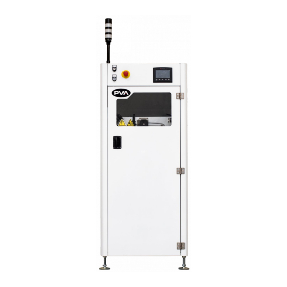
- Page 1 INNOVATION. PRECISION. EXCELLENCE. BI2000 Board Inverter Owner’s Manual Revision F 2 0 2 B...
- Page 2 BI2000 Board Inverter Manual T his document is based on information available at the time of its publication. While efforts 2 0 3 B have been made to ensure the contents of this manual are accurate, the information contained herein does not purport to cover all specific details or variations in hardware, or to provide for every possible contingency in connection with installation, operation, or maintenance.
-
Page 3: Table Of Contents
BI2000 Board Inverter Manual T able of Contents 4 5 7 B Introduction ......................6 3 9 1 B PVA Contact Information ......................6 4 0 1 B Document History ........................6 4 0 2 B Safety ............................7 4 0 3 B Notices and Warnings ...................... - Page 4 BI2000 Board Inverter Manual Auto Cycle ..........................16 4 1 7 B Manual Mode ..........................16 4 1 8 B Conveyor Operation ....................... 17 4 3 8 B Board Stops ........................17 4 3 9 B Rotate ..........................18 4 4 0 B SMEMA ..........................
- Page 5 BI2000 Board Inverter Manual Rotary Adjustment ........................ 30 4 2 6 B Rotation Angle ........................ 30 4 5 4 B Soft Start Adjustment ....................31 4 5 5 B Rotary Speed Adjustment ..................... 31 4 5 6 B Width Adjustment ........................32 4 2 7 B Main Air Regulator .........................
-
Page 6: Introduction
BI2000 Board Inverter Manual Introduction B efore you operate this system, read the operation and setup manual. This will help you to 2 0 9 B become familiar with the product and ensure successful operation. I f any questions or problems arise, contact PVA’s Technical Support department. -
Page 7: Safety
BI2000 Board Inverter Manual Safety C ertain warning symbols are affixed to the machine and correspond to notations in this 2 2 1 B manual. Before operating the system, identify these warning labels and read the notices described below. Not all labels may be used on any specific system. - Page 8 BI2000 Board Inverter Manual Do not smoke near the PVA UV cure machine. Always have a fire extinguisher available for emergency use. Before performing any repairs or maintenance to the system, turn off power and lock out the power disconnect switch.
-
Page 9: Notices And Warnings
BI2000 Board Inverter Manual Notices and Warnings • W ear safety glasses, gloves, and long-sleeved clothing when working with 7 7 B automated industrial equipment. • R ead and understand all operating manuals before using this equipment. 7 8 B •... -
Page 10: Temperature And Humidity
BI2000 Board Inverter Manual Temperature and Humidity O peration and storage should be done at 40–105°F (4–41°C) and low humidity. Do not let 2 2 7 B condensation collect on the machine. Install the system on a level surface, away from standing water, possible over spray, and overhead leaks. -
Page 11: Setup
BI2000 Board Inverter Manual Setup WARNING: These procedures should be done by a qualified person in accordance with this manual and applicable safety regulations. A “qualified person” is defined as “a person or persons who, by possession of a recognized degree or certificate or... -
Page 12: Air Pressure Regulator
BI2000 Board Inverter Manual Air Pressure Regulator T o adjust the system air pressure, pull up on the regulator knob so the orange ring 9 0 B can be seen. F igure 4: Pull Up on the Regulator to Adjust... -
Page 13: Safety Devices And Guarding
BI2000 Board Inverter Manual Safety Devices and Guarding Note: The safety features should NEVER be bypassed, disabled or tampered with. Precision Valve & Automation, Inc. is not responsible for any damages incurred because of alteration or destruction of any safety features. -
Page 14: Interface Overview
BI2000 Board Inverter Manual S tate R ed A mber G reen B uzzer 2 4 0 B 2 4 1 B 2 4 2 B 2 4 3 B 2 4 4 B C ycle Stop O FF O FF... -
Page 15: Operation
BI2000 Board Inverter Manual Operation Startup Procedure C heck the air pressure. 9 8 B C lose the door. 9 9 B E ngage the “Emergency Stop” button. 1 0 0 B U se the main power red rotary switch to turn on the system power. -
Page 16: Auto Cycle
BI2000 Board Inverter Manual Auto Cycle A uto Cycle is the normal operating mode for the PVA board inverter. In Auto Cycle, the 2 7 0 B machine operates as part of a production line and interfaces with any adjacent machines. -
Page 17: Conveyor Operation
BI2000 Board Inverter Manual Conveyor Operation F igure 10: Manual Mode, Conveyor Speed 4 9 B U se the Red X or the Green Checkmark button to toggle the conveyor “On” or 1 1 5 B “Off”. S elect the Direction: button to toggle between L to R (left to right) or R to L 1 1 6 B (Right to Left). -
Page 18: Rotate
BI2000 Board Inverter Manual Rotate F igure 12: Manual Mode, Rotate 5 1 B • T o manually rotate the cage, push the “Square Arrow Button” on-screen. The arrow 1 1 8 B direction shows the current position. W hen the arrow is Up the cage is in the home position (0 degrees) -
Page 19: Pip Status
BI2000 Board Inverter Manual PIP Status V iew the status of the part in place (PIP) input from the machine. 2 7 8 B F igure 14: Manual Mode, PIP Status 5 3 B Shutters T his screen only applies to systems with shutters. To manually open or close the shutters 2 8 0 B select the Green Checkmark or Red X. -
Page 20: Conveyor Width Adjust
BI2000 Board Inverter Manual Conveyor Width Adjust T his screen only applies to systems with automatic width adjust. 2 8 2 B • T o manually adjust the conveyor width, go to the Conveyor Width screen. 1 2 3 B •... -
Page 21: Flip Process
BI2000 Board Inverter Manual Flip Process T he screen below shows all available flip options, the arrows will change based on the 2 8 6 B board in and out directions selected. F igure 17: Flip Roll Cage 5 6 B S elect the “Board In”... -
Page 22: Board Second Flip
BI2000 Board Inverter Manual Board Second Flip S elect the 2nd Flip icon to toggle between “Yes” and “No” for the second flip board process. 2 9 0 B Conveyor Width T his is an optional setting. Not all modules will have this option. -
Page 23: Profile Naming
BI2000 Board Inverter Manual Profile Naming U se the arrows on the screen or the “F1” and “ESC” button to scroll to the Setup- 1 4 0 B Rename Profile screen. U se the + - Page icons or the F2 and F4 keys to scroll through the profile names. -
Page 24: Fault Recovery
BI2000 Board Inverter Manual Fault Recovery S everal errors can cause a fault condition: 2 9 4 B • “ Emergency Stop” is engaged 1 4 4 B • T he door is open 1 4 5 B • L ow air pressure (option) 1 4 6 B •... -
Page 25: Open Door Or "Emergency Stop" Recovery Procedure
BI2000 Board Inverter Manual Open Door or “Emergency Stop” Recovery Procedure I f the “Emergency Stop” button is engaged or there is a machine error, do this procedure. 2 9 7 B Do not continue if the “Emergency Stop” was engaged because of a system failure instead, shutdown the system and have it repaired by qualified personnel. -
Page 26: Recovery Procedure For Board Processing Failure
BI2000 Board Inverter Manual Recovery Procedure for Board Processing Failure A board processing failure can result from a board jam, or if the board is longer than the 2 9 9 B inverter can handle and the infeed and outfeed sensor are on at the same time. -
Page 27: Error Messages
BI2000 Board Inverter Manual Error Messages T he following are all the possible error messages generated by the PLC program. 3 0 3 B M SG # D escription 7 6 B 4 0 0 B D isengage Emergency Stop... -
Page 28: Maintenance
BI2000 Board Inverter Manual Maintenance I nterval A ction 3 2 8 B 3 2 9 B • W eekly C lean the sensors with a lint-free damp cloth. 3 3 0 B 1 6 7 B • M onthly M ake sure the conveyor belts are not worn. -
Page 29: Board Thickness Adjustment
BI2000 Board Inverter Manual Board Thickness Adjustment T his procedure will adjust the distance between the chains, there should be a 1mm gap 3 3 4 B between the board and the chain. The gap between the upper and lower conveyor chain is adjustable from 0.28”... -
Page 30: Rotary Adjustment
BI2000 Board Inverter Manual W hen the gap is correct, tighten the four shoulder bolts at the end of the turn 1 8 2 B buckle. R epeat the procedure for the rear conveyor rail. 1 8 3 B F igure 28: Conveyor Adjustment... -
Page 31: Soft Start Adjustment
BI2000 Board Inverter Manual Soft Start Adjustment T he soft start is attached to the main air pressure regulator and regulates the time it takes 3 4 0 B for the roll cage’s pneumatic manifold to reach pressure. If the pneumatic manifold is pressurized too quickly, the roll cage will rotate aggressively and slam into the hard stops. -
Page 32: Width Adjustment
BI2000 Board Inverter Manual Width Adjustment T o adjust the width of the rear conveyors on units that do not have the “Auto Adjust” 3 4 3 B option, perform the procedure below. Note: This is for systems that do not have automatic width adjust. -
Page 33: Main Air Regulator
BI2000 Board Inverter Manual Main Air Regulator • M ake sure there is no water in the bottom, drain as necessary. 2 0 1 B F igure 33: Main Air Regulator 7 2 B Page 33 of 37 Revision F... -
Page 34: Troubleshooting
BI2000 Board Inverter Manual Troubleshooting T roubleshooting P ossible Cause C orrective Action 7 3 B 7 4 B 7 5 B Problem T he machine is • • C ables are loose or not E xamine the cable connections... -
Page 35: Notes
BI2000 Board Inverter Manual Notes Page 35 of 37 Revision F January 2022... -
Page 36: Warranty
BI2000 Board Inverter Manual Warranty P VA Warranty Policy 3 4 7 B P VA warrants the enclosed product against defects in material or workmanship on all 3 4 8 B components for one year from the date of shipment. -
Page 37: Table Of Figures
BI2000 Board Inverter Manual Table of Figures 4 1 B F igures 1 and 2: Functional Block Diagram and SMEMA Cables and Process Flow ....10 3 5 9 B 4 2 B F igure 3: Main Air Attachment ......................11 3 6 0 B 4 3 B F igure 4: Pull Up on the Regulator to Adjust ..................
Need help?
Do you have a question about the BI2000 and is the answer not in the manual?
Questions and answers