Advertisement
Quick Links
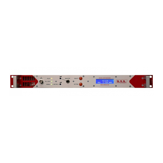
1 1
1 - IF SAMPLER 10,7MHz OUT 0dBm
2 - POWER SUPPLY CORRECT OPERATION YELLOW INDICATOR
3 - PLL LOCK FREQUENCY CONTROL CORRECT OPERATION CIRCUIT GREEN INDICATOR
4 - PRESENCE OF RF SIGNAL AT PROPER LEVEL AND FREQUENCY AT INPUT RF CONNECTOR
GREEN INDICATOR
5 - EARPHONE LEVEL ADJUSTING
6 - MUTING TRESHOLD ADJUSTING
7 - EARPHONE 6,3 mm MONITORING JACK CONNECTOR
8 - 9 - THESE PUSHBOTTONS ALLOW TO SELECT ON LCD DISPLAY THE FOLLOWING MENU:
- display parameters
- password
- change of receiving frequency
10 - LCD MULTIMETER DISPLAY SHOWING:
- operational frequency
- deviation of receiving signal
- signal strenght
FM STL RECEIVER
FRONT PANEL LAYOUT
2 2
5 5
3 3
6 6
7 7
4 4
8 8
10
10
9 9
T I T L E
T I T L E
FM LINK RECEIVER mod. BRAVO RX
front panel layout
D A T E
D A T E
12-2020
D R A W I N G N O .
D R A W I N G N O .
RVR Link Receiver front layout.cdr
Advertisement

Summary of Contents for R.V.R. Elettronica BRAVO-RX
- Page 1 FM STL RECEIVER FRONT PANEL LAYOUT 1 - IF SAMPLER 10,7MHz OUT 0dBm 2 - POWER SUPPLY CORRECT OPERATION YELLOW INDICATOR 3 - PLL LOCK FREQUENCY CONTROL CORRECT OPERATION CIRCUIT GREEN INDICATOR 4 - PRESENCE OF RF SIGNAL AT PROPER LEVEL AND FREQUENCY AT INPUT RF CONNECTOR GREEN INDICATOR 5 - EARPHONE LEVEL ADJUSTING 6 - MUTING TRESHOLD ADJUSTING...
-
Page 2: Rear Panel Layout
FM LINK RECEIVER REAR PANEL LAYOUT MONO MAINS 110-220 VAC AC FUSE 1A INPUT SCA 2 SCA 1 MPX OUT INTERLOCK RS232 1 - MAINS SUPPLY CONNECTOR 2 - AC FUSE 1A 3 - FAN 4 - DB 9 PIN INPUT / OUTPUT CONNECTOR FOR TELEMETRY ( opt.01 ) 5 - BNC FEMALE FOR CONNECTION OF THE INTERLOCK LOOP - THE CONNECTION GOES TO GROUND WHEN MUTE IS ON 6-7- BNC FEMALES FOR SUBCARRIERS OUTPUTS... -
Page 3: Usage Instruction
BRAVO-RX & BRAVO-TX USAGE INSTRUCTION... - Page 4 Connected a 50 Ω load or 50 Ω antenna to the RF output, connect the equipment into a mains supply (100÷240 VAC) with earth point. The transmitter equipment is factory pre-set to 0.0 W. Switch ON the power switch and the yellow V POWER led will light. The Display will show: SELECT WAIT...
- Page 5 SELECT MOD > 50dBuV To display the frequency push the SET key. In order to display the parameter push the SELECT key. Display Password The Password mode is factory set to enable, and is not possible change this SET. The default password is 1 2 3. The WAIT of changing the password is as follows: •...
-
Page 6: New Password
SELECT CONFIRM (Y/N) ? N=SEL. Y=SET. If the password is not corrected an error is displayed: SELECT ERROR PASSWORD After few seconds display will show again the parameters. • When the password is corrected the display will show: SELECT NEW PASS . = SEL . NEW FREQ . -
Page 7: Error Confirmation
SELECT STORED NEW PASSWORD If the confirmation password is wrong the display will show: SELECT ERROR CONFIRMATION IMPORTANT NOTE ! BE CAREFULLY ! Once the password is set, it must be remembered otherwise neither can the frequency be changed or a new password entered. Display Change of Frequency. - Page 8 When the five digit is changed the further press SET key confirm the new frequency. At this operation follows the WAIT cycle and after this the display will show the parameters: SELECT MOD > FRW 8.0W RFL 0.0W After 7 minutes the display light switch off and the display will show: SELECT R.V.R.
- Page 9 Environmental conditions for the installation Each equipment produced by our Company has been carefully designed and tested in compliance with the European normative. The reported marks placed in the rear panel and in the manual are relevant to the tests realized on the equipment according to rigorous safety criteria advised by the Country where the equipment will operate.
- Page 10 No material such as a rope, insulating material, or clothing should cover the equipment at any time. Make sure that no kind of materials or objects can somehow reduce the regular cooling air flow through the equipment. Before operating the equipment, make sure that all the advises reported in the manual are fully complied.
- Page 11 Package description Any equipment is always supplied by us inside a suitable package for a safe freighting, to avoid damages to the equipment due to small shocks. Basically, the package is a carton box sealed with adhesive tape with the manufacturer brand name, then externally tighten by a wide plastic cord.
- Page 12 Small equipment or spare modules are usually supplied with the following kind of package: 1) Carton box 2) Polythene bag 3) Polystyrene material to absorb mechanical shocks...
- Page 13 Installing operations The installation of any electrical equipment should be always made by technical and specifically trained technicians, who are supposed to be aware of the risks related to the connection to an electrical supply. Before proceeding to the installation, it is mandatory to verify that the general electrical supply is fully in compliance with the normative of the Country where the equipment will operate.
- Page 14 Disregarding the above mentioned advises and recommendations will bring damages to the internal components and risk of fire Make sure that the equipment is placed in a stable and secure position, to easily allow the access to the front panel and to the rear panel too. This will permit in the future a simple and fast inspection of the connections if they are necessary.
- Page 15 Maintenance and cleanness Routine maintenance and cleanness can be exclusively done when the equipment is not connected to the mains. Disregarding this caution, may have the effect of serious problems to the personal safety. For no reasons, the equipment should have any contacts with water or other liquids.
- Page 16 Safety Read this chapter carefully before installation and use of the equipment. Introduction The equipment described in this manual, has been designed for use by properly trained personnel only. Adjustment, maintenance and repair of the exposed equipment should only be carried out by qualified personnel who are aware of hazards involved.
- Page 17 If adjustment, maintenance, or repair of the opened instrument is unavoidable, it must only be carried out by a skilled person who is aware of the hazards involved. Caution and Warning Statements Caution Used to indicate correct operation or maintenance in order to prevent damage to, or destruction of equipment or other property.
- Page 18 The equipment is designed for the following environmental conditions: Indoor use Altitudes up to 2000 m Temperatures between +5 C and +45 Maximum relative humidity of 95% for temperatures up to 20 The equipment is equipped with a number of input and output terminals as described in the Chapter Product Data.
- Page 19 Symbols Symbol Colour: Explanation: High voltage terminal: a terminal at which a voltage, with respect to another terminal or parts exists or may be adjusted to 1000 V or more. (High voltage > 1000 V). Black/Yellow Live part shock risk of electric shock.
- Page 20 General safety recommendations When connecting the equipment to the power, please follow these important recommendations: This product is intended to operate from a power source that will not apply more than 10% of the voltage specified on the rear panel between the supply conductors or between either supply conductor and ground.
- Page 21 Good practices In maintaining the equipment described in this manual, please keep in mind the following, standard good practices: When connecting any instrument (wattmeter, spectrum ana- lyzer, etc.) to a high frequency output, use the appropriate atten- uator or dummy load to protect the final amplifiers and the in- strument input.
- Page 22 First AID in case of electrical shock If someone seems unable to free himself while receiving an electric shock, turn power off before rendering aid. A muscular spasm or unconsciousness can make a victim unable to free himself from the electrical power.
- Page 23 Step 4 Put the fingertips of your hand on the Adam's apple, slide them into the groove next to the windpipe. Feel for a pulse. If you can not feel a pulse or are unsure, move on to the next step. Step 5 Position your hands in the center of the chest between the nipples.
- Page 24 Cover burned surface with a clean dressing. Remove all clothing from the injured area, but cut around any cloth- ing that adheres to the skin and leave it in place. Keep the patient covered, except the injured part, since there is a tendency to chill. Splint all fractures.
- Page 25 IF DEMODULATOR MIXER AUDIO OUTPUT MONO MHz 59.3 MHz 10.7 Fo=70 MHz POWER SUPPLY INPUT MIXER DISPLAY TCXO R.V.R. 12.8 MICROCONTROLLER MHz XXX.000 Title Functional Schematic 200 - 960 MHz Size Document Number Mod. BRAVO-RX Date: Tuesday, January 12, 2021 Sheet...
- Page 26 RG176 Mather Board V-VCO +15V POWER SUPPLY FRONTAL PANEL CONTROL AUDIO MONITOR DISPLAY IF TEST VOLUME MUTE ON/OFF DISPLAY R.V.R. MHz XXX.000 Title General Schematic 200 - 960 MHz Size Document Number Mod. BRAVO-RX Date: Tuesday, January 12, 2021 Sheet...
- Page 27 0.8mH L IN L OUT 2.2nF / 350V GND EARTH GND EARTH 1uF / 350V 2.2nF / 350V 0.8mH N IN N OUT Title EMC FILTER Size Document Number Mod. EMC-02 Date: Tuesday, January 12, 2021 Sheet...
- Page 28 TERM1 +15V 220pF IF 70 MHz ACTIVE FILTER +15V +15V MIXER RFMX-1X 6.8pF V PLL V PLL RF OUT RF IN RF IN 47pF RF OUT RF PLL RF PLL Title VCO & ACTIVE FILTER 200 MHz Size Document Number Mod.
- Page 29 CHOKE CHOKE CHOKE +15V 0.1MF 100MF 47V 3.3pF RF IN 4T/8D 4T/8D 4T/8D 4T/8D 4T/8D 4T/8D RF OUT 3.3pF 3.3pF 3.3pF 3.3pF 3.3pF BFR91A BFR91A BFR91A 3.3pF 1.8÷10pF 3.3pF 1.8÷10pF 3.3pF 1.8÷10pF 3.3pF 1.8÷10pF 3.3pF 1.8÷10pF 3.3pF 1.8÷10pF Title Active Filter 200 MHz Size Document Number Mod.
- Page 30 U1 78M09 +15V 47MF/25V 100nF 100nF 100nF 2.2MF/16V 2.2MF/16V 100nF 100nF 0.33uH COAX1 UT085 2.2uH V PLL 50pF 10pF 22pF 22pF 22pF 4.7pF BB149 BB149 BB149 BB149 BB149 J310 4.7pF 100nF 10MF/35V 100nF 100nF 100nF RF OUT 100pF 3.3pF BFR93L 100pF 100pF 100pF...
- Page 31 Part List Schematic : Active Filter 200 MHz Rif. Value Remarks Description Code Ceramic Lead Through Capacitor Ceramic Lead Through Capacitor Ceramic Lead Through Capacitor 100MF Aluminium Electrolytic Capacitor 0.1MF Multilayer Ceramic Capacitor 3.3pF Ceramic Disc Capacitor 3.3pF Ceramic Disc Capacitor 3.3pF Ceramic Disc Capacitor 3.3pF...
- Page 33 Part List Schematic : VCO 200 MHz Rif. Value Remarks Description Code 47MF Aluminium Electrolytic Capacitor 100nF SMD Multilayer Ceramic Capacitor 100nF SMD Multilayer Ceramic Capacitor SMD Multilayer Ceramic Capacitor 2.2MF SMD Aluminium Electrolytic Capacitor 2.2MF SMD Aluminium Electrolytic Capacitor 100nF SMD Multilayer Ceramic Capacitor 100nF...
- Page 34 Rif. Value Remarks Description Code 1/4W SMD Thick Film Resistor BB149 SMD Tuning Diode BB149 SMD Tuning Diode BB149 SMD Tuning Diode BB149 SMD Tuning Diode BB149 SMD Tuning Diode Fixed Voltage Regulator 78M09 J310 JFET BFR93L SMD RF Bipolar Transistor BFR93L SMD RF Bipolar Transistor COAX1...
- Page 35 TERM1 47MF / 16V +15V 10pF IF 70 MHz LM7805 +15V MIXER RFMX-1X 47MF / 16V 10pF V PLL V PLL 3.3pF 47pF 10pF 1T/4D RF OUT RF IN 1T/4D 1T/4D BFR91A RF PLL RF PLL 1T/4D 10pF 1.8÷10pF 1.8÷10pF 1.8÷10pF 1.8÷10pF Title...
- Page 36 68pF 68pF 47nH MGA62563 68pF 4.7nH RF INPUT RF OUTPUT 68pF Title RF low noise amplifier Size Document Number Mod. A2G Date: Tuesday, January 12, 2021 Sheet...
- Page 37 U1 78M09 TERM1 +15V 100nF 47MF/25V 100nF 100nF 2.2MF/16V 2.2MF/16V 100nF 100nF 0.33uH COAX1 UT085 TERM2 2.2uH V-PLL 50pF 10pF 22pF 22pF 22pF 4.7pF BB149 BB149 BB149 BB149 BB149 J310 4.7pF 100nF 10MF/35V 100nF 100nF TERM3 100nF RF-OUT 100pF 3.3pF BFR93L TERM4 100pF...
- Page 38 Part List Schematic : Active Filter & Mixer 300 MHz Rif. Value Remarks Description Code Ceramic Disc Capacitor NPO Ceramic Disc Capacitor NPO 10pF Ceramic Disc Capacitor NPO 10pF Ceramic Disc Capacitor NPO 3.3pF Ceramic Disc Capacitor NPO 10pF Ceramic Disc Capacitor NPO 10pF Ceramic Disc Capacitor NPO 1.8÷10pF...
- Page 40 Part List Schematic : A2G Rif. Value Remarks Description Code 68pF SMD Multilayer Ceramic Capacitor SMD Multilayer Ceramic Capacitor 68pF SMD Multilayer Ceramic Capacitor 68pF SMD Multilayer Ceramic Capacitor 68pF SMD Multilayer Ceramic Capacitor SMD Multilayer Ceramic Capacitor SMD Multilayer Ceramic Capacitor 47nH SMD Inductor 4.7nH...
- Page 42 Part List Schematic : VCO 300 MHz Rif. Value Remarks Description Code 47MF Aluminium Electrolytic Capacitor 100nF SMD Multilayer Ceramic Capacitor 100nF SMD Multilayer Ceramic Capacitor SMD Multilayer Ceramic Capacitor 2.2MF SMD Aluminium Electrolytic Capacitor 2.2MF SMD Aluminium Electrolytic Capacitor 100nF SMD Multilayer Ceramic Capacitor 100nF...
- Page 43 Rif. Value Remarks Description Code 1/4W SMD Thick Film Resistor BB149 SMD Tuning Diode BB149 SMD Tuning Diode BB149 SMD Tuning Diode BB149 SMD Tuning Diode BB149 SMD Tuning Diode Fixed Voltage Regulator 78M09 J310 JFET BFR93L SMD RF Bipolar Transistor BFR93L SMD RF Bipolar Transistor COAX1...
- Page 44 TERM1 47MF / 16V +15V 10pF IF 70 MHz LM7805 +15V MIXER RFMX-1X 47MF / 16V 10pF V PLL V PLL 3.3pF 47pF 10pF 1T/4D RF OUT RF IN 1T/4D 1T/4D BFR91A RF PLL RF PLL 1T/4D 10pF 1.8÷10pF 1.8÷10pF 1.8÷10pF 1.8÷10pF Title...
- Page 45 68pF 68pF 47nH MGA62563 68pF 4.7nH RF INPUT RF OUTPUT 68pF Title RF low noise amplifier Size Document Number Mod. A2G Date: Tuesday, January 12, 2021 Sheet...
- Page 46 U1 78L09 +15V 0.1MF 47MF / 35V 0.1MF 0.1MF 0.1MF 2.2MF / 50V 0.1MF CHOKE RF-FERRITE COAX1 UT085 10-50pF 2.2uH V PLL 1.8-10pF J310 22pF 22pF 22pF 4.7pF BB505 BB505 BB505 BB505 BB505 4.7pF 100pF RF PLL 0.1MF 2.2MF / 50V 0.1MF 10MF / 35V 0.1MF...
- Page 47 Part List Schematic : Active Filter & Mixer 400 MHz Rif. Value Remarks Description Code Ceramic Disc Capacitor NPO Ceramic Disc Capacitor NPO 10pF Ceramic Disc Capacitor NPO 10pF Ceramic Disc Capacitor NPO 3.3pF Ceramic Disc Capacitor NPO 10pF Ceramic Disc Capacitor NPO 10pF Ceramic Disc Capacitor NPO 1.8÷10pF...
- Page 49 Part List Schematic : A2G Rif. Value Remarks Description Code 68pF SMD Multilayer Ceramic Capacitor SMD Multilayer Ceramic Capacitor 68pF SMD Multilayer Ceramic Capacitor 68pF SMD Multilayer Ceramic Capacitor 68pF SMD Multilayer Ceramic Capacitor SMD Multilayer Ceramic Capacitor SMD Multilayer Ceramic Capacitor 47nH SMD Inductor 4.7nH...
- Page 51 Part List Schematic : VCO 400 MHz Rif. Value Remarks Description Code 47MF Aluminium Electrolytic Capacitor 0.1MF SMD Multilayer Ceramic Capacitor 0.1MF SMD Multilayer Ceramic Capacitor SMD Multilayer Ceramic Capacitor 2.2MF SMD Aluminium Electrolytic Capacitor 0.1MF SMD Multilayer Ceramic Capacitor 0.1MF SMD Multilayer Ceramic Capacitor 10-50pF...
- Page 52 Rif. Value Remarks Description Code BB134 SMD Tuning Diode BB134 SMD Tuning Diode BB134 SMD Tuning Diode BB134 SMD Tuning Diode BB134 SMD Tuning Diode 78L09 Fixed Voltage Regulator J310 JFET BFR93L SMD RF Bipolar Transistor BFR93L SMD RF Bipolar Transistor COAX1 UT085 Resonant coaxial line...
- Page 53 TERM1 +15V 220pF IF 70 MHz ACTIVE FILTER +15V +15V MIXER RFMX-1X 6.8pF V PLL V PLL RF OUT RF IN RF IN 47pF RF OUT RF PLL RF PLL RF AUX Title VCO & ACTIVE FILTER 900 MHz Size Document Number Mod.
- Page 54 +15V 10pF 22pF RF INPUT RF OUTPUT Low Noise Amplifier +15V 3.3pF RF INPUT RF OUTPUT BFR91A 1 ÷ 10 pF 1 ÷ 10 pF 1 ÷ 10 pF 1 ÷ 10 pF Title Active Filter Size Document Number Mod. AFILT900 Date: Tuesday, January 12, 2021 Sheet...
- Page 55 +15V 100nF 2.2MF / 16V RF OUTPUT 10pF RF INPUT BFG540 BFG540 Title Low Noise Amplifier Size Document Number Mod. AMPLN900 Date: Tuesday, January 12, 2021 Sheet...
- Page 56 U1 LM7809 U2 LM78L05 100nF +15V 10MF / 25V 10MF / 25V 100nF 10MF / 25V 22uH 100nF 100nF 100nF 100nF 100nF 100nF 33nH MCL25 22uH 47pF GND-5 RF OUT 10pF 22pF 22pF 47pF 47pF GND-1 GND-4 BFG198 GND-2 GND-3 BFG198 3.3pF ERA1...
- Page 57 Part List Schematic : Active Filter & Mixer 900 Rif. Value Remarks Description Code Ceramic Lead Through Capacitor 220pF Ceramic Disc Capacitor NPO 6.8pF Ceramic Disc Capacitor NPO 47pF Ceramic Disc Capacitor NPO Ceramic Lead Through Capacitor Ceramic Disc Capacitor NPO 10pF Ceramic Disc Capacitor NPO 22pF...
- Page 59 Part List Schematic : Low Noise Amplifier 900 MHz Rif. Value Remarks Description Code 2.2MF SMD Tantalum Capacitor 100nF SMD Multilayer Ceramic Capacitor 10pF SMD Multilayer Ceramic Capacitor SMD Multilayer Ceramic Capacitor 1/8W SMD Thick Film Resistor 1/8W SMD Thick Film Resistor 1/8W SMD Thick Film Resistor 1/8W...
- Page 61 Part List Schematic : VCO 900 MHz Rif. Value Remarks Description Code 100nF SMD Multilayer Ceramic Capacitor 10MF SMD Tantalum Capacitor 10MF SMD Tantalum Capacitor 10MF SMD Tantalum Capacitor 100nF SMD Multilayer Ceramic Capacitor 100nF SMD Multilayer Ceramic Capacitor 100nF SMD Multilayer Ceramic Capacitor 100nF SMD Multilayer Ceramic Capacitor...
- Page 62 Rif. Value Remarks Description Code SMD Thick Film Resistor BB149 SMD Tuning Diode BB149 SMD Tuning Diode BFG198 SMD RF Bipolar Transistor BFG198 SMD RF Bipolar Transistor LM7809 Fixed Voltage Regulator LM78L05 Fixed Voltage Regulator MCL25 RF low power amplifier ERA1 RF low power amplifier CRES1...
- Page 64 MUTING DEMODULATOR AUDIO CIRCUITS +15V SIGNAL LED +15V OUTPUT 10.7 MHz +15V +15V SIGNAL LED +15V +15V INTERLOCK INTERLOCK IF TEST -15V -15V MONO +MONO -15V A-MUTE + HEADPHONE -15V A-MUTE +HEADPHONE POWER SUPPLY B-MUTE INPUT 70 MHz - HEADPHONE B-MUTE -HEADPHONE C-MUTE...
- Page 65 LL4148 LT1374CR C109 10uH C114 220nF 47MF / 16V SHDN BOOST R140 R141 R142 270K 10uH MMBS340T3 C237 -15V 1.5nF C113 47MF / 16V R143 R144 C118 R145 C117 100nF 100MF / 25V C110 C111 C112 C115 C116 -15V GND_AN 10MF / 25V 10MF / 25V 10MF / 25V...
- Page 66 IF 70 MHz IF 10.7 MHz +15V +15V +15V SIGNAL IF TEST 10.7 MHz OUTPUT IF OUT IF IN INPUT 70 MHz 70 MHz INPUT AUDIO OUTPUT AUDIO OUTPUT Title DEMODULATOR Size Document Number Mod. MAIN.RX Date: Tuesday, January 12, 2021 Sheet...
- Page 67 R205 +15V 10.7 MHz OUTPUT C177 C178 C175 C176 C179 C180 100nF 47MF / 16V 47MF / 16V 100nF R206 R207 BSL-1X C181 100pF C182 70 MHz FILTER 470nH IN RF R208 C183 C184 6.8pF GND IN RF R209 C246 C185 470nH OUT RF...
- Page 68 10.7 MHz R216 3K9 R217 DEMI2 DEMI1 +15V C196 100nF n.c. n.c. C197 C198 C199 C195 100nF R218 100nF R219 100nF R220 C194 100nF 100MF / 16V R221 MODE R222 AUDIO OUTPUT SHUNT R224 C200 MUTE VREF 100nF R223 10.7 MHz 10.7 MHz 10.7 MHz VoAF...
- Page 69 MONITOR A-VOLUME B-VOLUME C-VOLUME +15V A-VOLUME B-VOLUME C-VOLUME AUDIO Audio FIlters +HEADPHONE + HEADPHONE +15V - HEADPHONE -HEADPHONE -15V MPX OUTPUT AUDIO OUTPUT AUDIO INPUT +15V MONO OUTPUT AUDIO -15V +15V +15V +MONO + MONO -15V -MONO -15V - MONO AUDIO INPUT AUDIO INPUT AUDIO OUPUT...
- Page 70 +RELE -RELE RELE 1 SCAMBIO LF347 AUDIO INPUT 22MF / 16V 22MF / 16V 10pF 100K 100K 7-50pF 560K 4.7pF LF347 +15V AUDIO OUPUT 100nF 10MF / 16V 100nF -15V 100nF 10MF / 16V 100nF Title AUDIO Size Document Number Mod.
- Page 71 C164 220pF 100pF 680pF 2.2nF 56pF 560pF 10pF C165 100pF LF347 47pF 8.2pF 2.7pF 82pF LF347 LF347 LF347 MPX OUTPUT 3.9pF 68pF 3.3pF 1.5pF 150pF 12pF 220pF 56pF 2.2pF 470K 47pF 33pF 10pF 4.7pF 180K 220K AUDIO INPUT 2.7nF 3.3nF 330K 33nF 39nF...
- Page 72 +15V R112 R113 C247 2.2MF / 50V AUDIO 100nF 10MF / 35V R114 560K R115 A-VOLUME C100 R116 LM386 100MF / 16V + HEADPHONE C102 10MF / 35V R117 R118 - HEADPHONE B-VOLUME C-VOLUME C101 10MF / 35V C103 47nF Title MONITOR Size...
- Page 73 LF347 220MF / 16V 220MF / 16V 22uH LF347 C238 C239 100K 39pF 39pF MPX INPUT 100K 10pF 15pF LF347 LF347 100MF / 16V 100MF / 16V 22uH + MONO C240 C241 100K 39pF 39pF 100K MONO INPUT 4.7nF 50µs 82pF 100MF / 16V 100MF / 16V...
- Page 74 +15V C228 C229 C226 C227 100nF 100nF 10MF / 35V 10MF / 35V R249 LL4148 -15V INTERLOCK R250 R251 R252 ENABLE BC817-25L BC807-25L R253 R254 C230 R255 C231 R256 R257 U18B 2.2MF / 50V LM358 R258 SIGNAL LL4148 BC807-25L R259 C232 100nF R260...
- Page 75 AUDIO R119 R120 100K C104 DEVIATION METER R121 100pF R124 R122 C105 C106 R123 560K 0.47MF / 63V C107 100nF R126 R125 LM358 LL4148 R127 100K R128 R129 150K R130 SIGNAL R132 R131 LM358 R133 100K SIGNAL METER C108 R134 2.2MF / 50V 220K R135...
- Page 76 LCD1 DISPLAY V20350 11.0592MHz C131 C132 C133 10MF / 35V 100nF 33pF R158 10K VU Meter R159 10K C134 R160 10K 33pF R161 10K Signal MAX810L Auxiliary SDTA SCLK D[0:7] Vref OUT ADC_EN Vref IN Temperature AGND SARS C135 DGND 22MF / 16V C137 100nF...
- Page 77 TCXO1 C151 C149 C150 C152 MHz 12.800 100nF 10MF / 35V 22MF / 16V 100nF +15V C154 C153 R176 R177 100nF 2.2MF / 50V R178 R179 C155 C156 22MF / 16V 100nF BC807-25L C157 LL4148 LMX1501 R180 R181 OSCin ØR U14B R182 R183...
- Page 78 Part List Schematic : RAG-1B Rif. Value Remarks Description Code 39pF SMD Multilayer Ceramic Capacitor 39pF SMD Multilayer Ceramic Capacitor 22MF SMD Aluminium Electrolytic Capacitor 22MF SMD Aluminium Electrolytic Capacitor 10pF SMD Multilayer Ceramic Capacitor SMD Multilayer Ceramic Capacitor 7-50pF SMD Trimmer Capacitor 4.7pF SMD Multilayer Ceramic Capacitor...
- Page 79 Rif. Value Remarks Description Code 2.2nF SMD Multilayer Ceramic Capacitor 10pF SMD Multilayer Ceramic Capacitor 330pF SMD Multilayer Ceramic Capacitor 68pF SMD Multilayer Ceramic Capacitor 180pF SMD Multilayer Ceramic Capacitor 27pF SMD Multilayer Ceramic Capacitor 150pF SMD Multilayer Ceramic Capacitor 100pF SMD Multilayer Ceramic Capacitor 120pF...
- Page 80 Rif. Value Remarks Description Code C103 47nF SMD Multilayer Ceramic Capacitor C104 100pF SMD Multilayer Ceramic Capacitor C105 0.47MF SMD Aluminium Electrolytic Capacitor C106 2.2MF SMD Multilayer Ceramic Capacitor C107 100nF SMD Multilayer Ceramic Capacitor C108 2.2MF SMD Aluminium Electrolytic Capacitor C109 220nF SMD Multilayer Ceramic Capacitor...
- Page 81 Rif. Value Remarks Description Code C155 22MF SMD Aluminium Electrolytic Capacitor C156 100nF SMD Multilayer Ceramic Capacitor C157 SMD Multilayer Ceramic Capacitor C158 C159 22MF SMD Aluminium Electrolytic Capacitor C160 2.2MF SMD Aluminium Electrolytic Capacitor C161 22MF SMD Aluminium Electrolytic Capacitor C162 100nF SMD Multilayer Ceramic Capacitor...
- Page 82 Rif. Value Remarks Description Code C208 47MF SMD Aluminium Electrolytic Capacitor C209 100nF SMD Multilayer Ceramic Capacitor C210 3.3pF SMD Multilayer Ceramic Capacitor C211 100nF SMD Multilayer Ceramic Capacitor C212 220pF SMD Multilayer Ceramic Capacitor C213 220pF SMD Multilayer Ceramic Capacitor C214 100nF SMD Multilayer Ceramic Capacitor...
- Page 83 Rif. Value Remarks Description Code 22uH SMD Inductor 22uH SMD Inductor 22uH SMD Inductor 470nH SMD Inductor 1/4W SMD Thick Film Resistor 1/4W SMD Thick Film Resistor 1/4W SMD Thick Film Resistor 1/4W SMD Thick Film Resistor 1/4W SMD Thick Film Resistor 1/4W SMD Thick Film Resistor 1/4W...
- Page 84 Rif. Value Remarks Description Code 1/4W SMD Thick Film Resistor 1/4W SMD Thick Film Resistor 1/4W SMD Thick Film Resistor 1/4W SMD Thick Film Resistor 1/4W SMD Thick Film Resistor 1/4W SMD Thick Film Resistor 1/4W SMD Thick Film Resistor 680K 1/4W SMD Thick Film Resistor...
- Page 85 Rif. Value Remarks Description Code R100 1/4W SMD Thick Film Resistor R101 1/4W SMD Thick Film Resistor R102 1/4W SMD Thick Film Resistor R103 1/4W SMD Thick Film Resistor R104 1/4W SMD Thick Film Resistor R105 1/4W SMD Thick Film Resistor R106 1/4W SMD Thick Film Resistor...
- Page 86 Rif. Value Remarks Description Code R152 1/4W SMD Thick Film Resistor R153 1/4W SMD Thick Film Resistor R154 1/4W SMD Thick Film Resistor R155 1/4W SMD Thick Film Resistor R156 1/4W SMD Thick Film Resistor R157 1/4W SMD Thick Film Resistor R158 1/4W SMD Thick Film Resistor...
- Page 87 Rif. Value Remarks Description Code R204 1/4W SMD Thick Film Resistor R205 1/4W SMD Thick Film Resistor R206 1/4W SMD Thick Film Resistor R207 1/4W SMD Thick Film Resistor R208 1/4W SMD Thick Film Resistor R209 1/4W SMD Thick Film Resistor R210 1/4W SMD Thick Film Resistor...
- Page 88 Rif. Value Remarks Description Code R256 1/4W SMD Thick Film Resistor R257 1/4W SMD Thick Film Resistor R258 1/4W SMD Thick Film Resistor R259 1/4W SMD Thick Film Resistor R260 1/4W SMD Thick Film Resistor R261 1/4W SMD Thick Film Resistor R262 220K 1/4W...
- Page 89 Rif. Value Remarks Description Code LM358 SMD Operational Amplifier LT1374CR Special Function Integrated Circuit 78M09 Fixed Voltage Regulator 78M05 Fixed Voltage Regulator ADC0834CCWM Special Function Integrated Circuit MAX810L Special Function Integrated Circuit HIN232ACBN Special Function Integrated Circuit T89C51RD2 Special Function Integrated Circuit LM358 SMD Operational Amplifier LMX1501...
- Page 90 Rif. Value Remarks Description Code AUDIO PCB Pin Strip Header FILTERS PCB Pin Strip Header OUT MPX PCB Pin Strip Header 50/75 uS PCB Pin Strip Header SETUP PCB Pin Strip Header PROG PCB Pin Strip Header TEST Freq. PCB Pin Strip Header FM MODE PCB Pin Strip Header PCB Pin Strip Header...
- Page 93 JACK STEREO MONITOR V POWER PLL LOCK SIGNAL VOLUME MUTE SELECT SETTING DJ2x8 SIGNAL LED LOCK LED A-MUTE B-MUTE VDC LED C-MUTE + HEADPHONE SETTING - HEADPHONE SELECT A-VOLUME C-VOLUME B-VOLUME JA1A CONN ASY EDGE 16 Title FRONTAL PANEL Size Document Number Mod.
- Page 94 Part List Schematic : FP-RX Rif. Value Remarks Description Code Cermet Skeleton Trimmer Resistor Cermet Skeleton Trimmer Resistor V POWER Light Emitting Diode PLL LOCK Light Emitting Diode SIGNAL Light Emitting Diode DJ2x8 Male PCB Mounting Header JACK STEREO Jack Connector PCB Pin Strip Header SELECT Push Button Switcher...
Need help?
Do you have a question about the BRAVO-RX and is the answer not in the manual?
Questions and answers