Table of Contents

Related Manuals for NAL A3LA-R


Summary of Contents for NAL A3LA-R
- Page 1 451-93156-001A Model A3LA-R User Guide Version A April 1, 2022 Copyright © 2021 by NAL Research Corporation Powered by 11100 Endeavor Ct., Suite 300 Manassas, Virginia 20109 USA Phone: 703-392-1136 Email: contact@nalresearch.com...
- Page 2 Product (including hardware, software and/or firmware) and/or the Iridium satellite to the fullest extent these damages may be disclaimed by law and whether advised of the possibilities of such damages. NAL Research is not liable for any claim made by a third party or made by you for a third party.
- Page 3 A3LA-R User Guide Version A EVISION ISTORY Revision Date Description 04/08/2013 Initial version 07/14/2021 Updated to new template; proofread. 04/01/2022 Formal release Document Number: 451-93156-001A 3 of 158...
- Page 4 A3LA-R User Guide Version A EFERENCE OCUMENTS The latest revisions of the NAL documents are available from the NAL Research website at https://www.nalresearch.com/support/documentation-downloads/. Reference Title Revision/Date A3LA-R Product Information Getting Started With Model A3LA-R (TN2012-11-V1.0) Version 1.0, 2012 SatTerm Software Manual (451-94000-001A)
-
Page 5: Table Of Contents
A3LA-R User Guide Version A ABLE OF ONTENTS Introduction ......................16 Multi-Interface Connector ..................17 RS232 Data Interface (Standard 9-Wire Configuration) ............. 18 RS232 Data Interface (3-Wire Configuration) ..............18 DC Power Input ........................19 Power On/Off Control ......................20 Audio Interface ........................ - Page 6 A3LA-R User Guide Version A Wn – Error Correction Message Control................37 Zn – Soft Reset ........................37 B.10 &Cn – DCD Option ....................... 37 B.11 &Dn – DTR Option ....................... 37 B.12 &Fn – Restore Factory Settings ................... 38 B.13 &Kn –...
- Page 7 A3LA-R User Guide Version A B.40 +CMGW – Write SMS Message To Memory ............... 52 B.41 +CMOD – Call Mode ......................53 B.42 +CNMI – New SMS Message Indications to DTE ..............53 B.43 +COPS – Operator Select ....................55 B.44 +CPBF –...
- Page 8 A3LA-R User Guide Version A B.71 –MSVTS – DTMF Generation in Voice Call ................71 B.72 –MSVTR – DTMF Received in Voice Call ................72 B.73 –MSVLS – Local DTMF Feedback Selection ................. 72 B.74 –MSSTM – Request System Time ..................73 B.75 –MSGEO –...
- Page 9 A3LA-R User Guide Version A B.103 +SBDWT – Short Burst Data: Write a Text Message ............94 B.104 +SBDDET – Short Burst Data: Detach .................. 95 B.105 +SBDI – Short Burst Data: Initiate an SBD Session .............. 96 B.106 +SBDIX[A] – Short Burst Data: Initiate an SBD Session Extended........98 B.107 +SBDDSC –...
- Page 10 A3LA-R User Guide Version A Unit Identification ......................133 Setting the Default Configuration ..................133 Power on to Send an SBD Message .................. 134 SBD Automatic Notification Registration ................135 SBD Automatic Notification Message Reception .............. 135 SBD Automatic Notification Automatic Registration ............136 Originate a Data Call ......................
- Page 11 ABLE OF IGURES Figure 1: Iridium Satellite Modem A3LA-R ................... 16 Figure 2: Power Input Setting for the A3LA-R ................20 Figure 3: Location of the SIM Reader ................... 22 Figure 4: Location of the SIM Reader ................... 25 Figure 5: Iridium Satellite Modem A3LA-R ................... 26 Figure 6: Average Current Drawn During Standby ..............
- Page 12 A3LA-R User Guide Version A ABLE OF ABLES Table 1: Pin Assignments for the Multi-interface Connector ............17 Table 2: General RF Parameters ....................23 Table 3: Custom Antenna Specifications ..................23 Table 4: Numeric and Verbose Modes ..................35 Table 5: Standard S-Registers .....................
- Page 13 A3LA-R User Guide Version A LOSSARY ASCII ......American Standard Code for Information Interchange AT .......Two-letter sequence starting a string of terminal commands. The AT is intended to get the terminal’s attention prior to executing a command. BIS.......Bureau of Industry and Security bps ......bits per second...
- Page 14 A3LA-R User Guide Version A GPS ......Global Positioning System GSM ......Global System for Mobile Communications GSS ......Gateway SBD Subsystem IMEI ......International Mobile Equipment Identification I/O ......Input / Output IRLP ......Iridium Radio Link Protocol IP ........Internet Protocol IP67 ......Ingress Protection 67 ISU ......Iridium Subscriber Unit (modems, phones, trackers)
- Page 15 A3LA-R User Guide Version A RUDICS .......Router-based Unrestricted Digital Internetworking Connectivity Solution SatTerm ......Satellite Terminal emulator software SBD ......Short Burst Data SIM ......Subscriber Identification Module SM ......Short Message SME ......Short Message Entity SMS ......Short Message Service SMS-PP .......Short Message Service—Point to Point TCP ......Transmission Control Protocol...
-
Page 16: Introduction
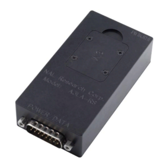
TNC Antenna Connector DB25 Multi-Interface Connector Figure 1: Iridium Satellite Modem A3LA-R IMPORTANT: Do not disassemble the A3LA-R for repair or services. The warranty is voided if the A3LA-R is disassembled. Return to NAL Research for any services. Document Number: 451-93156-001A... -
Page 17: Multi-Interface Connector
A3LA-R User Guide Version A ULTI NTERFACE ONNECTOR The multi-interface connector is a male 25-pin miniature D-Sub type (see Figure 1) that includes five interfaces—RS232, DC input power, ON/OFF control line, analog audio, and Digital Peripheral Link (DPL). The multi-interface connector pin assignments are summarized in Table 1, which is ‘pin-to-pin’. -
Page 18: Rs232 Data Interface (Standard 9-Wire Configuration)
Normally this is set to ‘+’ in register S2 (see Appendix A: AT Interface for details). Note that the Ring Indicator is used by the A3LA-R to indicate that a mobile-terminated SBD (MT-SBD) message is queued at the gateway. Application developers can monitor this pin and apply appropriate AT commands to the A3LA-R to retrieve the MT-SBD message. -
Page 19: Dc Power Input
A3LA-R as short as possible to prevent significant voltage drop, which can cause the A3LA-R to malfunction during a data call, an SMS session, or an SBD session. Power reset by the A3LA-R during a call indicates the DC power source is unable to sustain voltage above 4.0 V at... -
Page 20: Power On/Off Control
With the A3LA-R held in the position shown in Figure 2 (DB25 connector to the left), the A3LA-R is set for 4.0 V to +5.5 V when the red jumper is on the middle and left pins, and it is set for +5.0 V to +32 V when the jumper is on the middle and right pins. -
Page 21: Audio Interface
A3LA-R on and off in a toggle fashion. With this setup, the EXT_ON_OFF line MUST first be held to GND level (i.e., logic low) before applying power to the A3LA-R. As long as DC power input is applied, logic high on the EXT_ON_OFF line turns the A3LA-R on, and a logic low turns it off. -
Page 22: Digital Peripheral Link (Dpl)
A3LA-R User Guide Version A A3LA-R Modem DPL Handset HRC-24-8R Data Kit Figure 3: Location of the SIM Reader (DPL) IGITAL ERIPHERAL The DPL interface is composed of two ports—a full duplex asynchronous serial link for control messages and a PCM digital audio link for audio traffic. The protocol used on these ports is made available to application developers only on a case-by-case basis and after appropriate non-disclosure agreements and/or license agreements are executed. -
Page 23: Antenna Connector
NTENNA ONNECTOR The A3LA-R modem uses a single TNC female 50-ohm connector to both transmit and receive. Cable loss between the modem and the antenna is critical and must be kept less than 3 dB at the operating frequency of 1616 to 1626.5 MHz. The minimum link margin of 12 dB must also be maintained. - Page 24 A3LA-R User Guide Version A 2. Each bar represents a 2 dB increment. 3. Multiple ring channels can be present at the same time, so units can lock to different signals. 4. If the reading is near the decision threshold, it would be easy to see a 1-bar difference.
-
Page 25: Sim Card Interface
4 SIM C NTERFACE The A3LA-R modem contains an integrated Subscriber Identification Module (SIM) reader. The modem uses and requires an Iridium SIM chip for operation. The SIM chip is inserted into the opening located at the top of the modem, as shown in Figure 4. A plastic locking mechanism is used hold the SIM in place. -
Page 26: Led Display
A3LA-R User Guide Version A 5 LED D ISPLAY The A3LA-R has a status LED depicted as P for power indicator (see Figure 5). It provides a quick visual check to ensure power is provided to the modem. Power LED... -
Page 27: Configuration Settings
These profiles can be designated to be loaded as the active configuration upon A3LA-R power-up with the AT&Yn command. o The A3LA-R can be reset without loss of power to these profiles with the ATZn command. o The configuration settings are stored in “S-register” locations and are detailed in Appendix A: AT Interface. -
Page 28: Modes Of Operation
ODES OF PERATION The A3LA-R serial data port is always in one of three modes: command mode, SBD data mode, or SBD session mode. When the data port is in command mode, AT commands can be entered to control the A3LA-R. In command mode, flow control has no effect, so the RTS input ignored and the CTS output driven ON (low). -
Page 29: Mounting Recommendations
A3LA-R User Guide Version A OUNTING ECOMMENDATIONS The A3LA-R has four features on its bottom surface that can aid in its mounting (see Appendix L: Mechanical Drawing). These four features are predrilled at a minimum depth of 0.25 inch to accept 6-32 thread type. -
Page 30: Technical Support
For technical support, please contact us at: Phone: 703-392-1136, x203 Fax: 703-392-6795 Email: contact@nalresearch.com Technical documents are also available to download on NAL Research’s website www.nalresearch.com in the Support > Documentation & Downloads section. Document Number: 451-93156-001A 30 of 158... -
Page 31: Appendix A: At Interface
“No action, compatibility only.” In these cases, the basic command is accepted in the same fashion as it is with other modems, but has no effect on the operation of the A3LA-R because it has no meaning in the Iridium environment. - Page 32 For example, AT+GSN is entered as shown to query the A3LA-R for its assigned serial number (i.e., IMEI). Some extended commands incorporate a test mode to query their range of valid responses. Some extended commands incorporate set, read, and test modes.
-
Page 33: Command And Response Characters
OMMAND NTRY An AT command is a string of characters sent by the DTE to the A3LA-R while it is in command mode. A command string has a prefix, a body, and a terminator. The prefix consists of the ASCII characters AT or at. -
Page 34: Command Responses
Result codes can be represented by text if the A3LA-R is in verbose mode or with numbers if in numeric mode. The command ATVn informs the A3LA-R whether to respond in verbose or... -
Page 35: Hardware Failure Reporting
AILURE EPORTING If the A3LA-R detects a hardware problem during initialization, it may be unable to function correctly. The A3LA-R notifies the DTE of this situation by issuing an unsolicited result code at the end of initialization: HARDWARE FAILURE: <subsys>,<error>... -
Page 36: Appendix B: At Command Set Description
This is the prefix for all commands except A/ and +++. When entered on its own, the A3LA-R will respond OK. A/ – R EPEAT OMMAND Repeat the last command issued to the A3LA-R unless the power was interrupted or the unit is reset. A/ is not followed by <CR>. +++ – E SCAPE EQUENCE The escape sequence is used to transfer from in-call data mode to in-call command mode without disconnecting from the remote modem. -
Page 37: Vn - Verbose Mode
A3LA-R User Guide Version A – V ERBOSE Set the response format of the A3LA-R, which may be either numeric or textual. Numeric responses Textual responses (default) – E RROR ORRECTION ESSAGE ONTROL Set the format of the CONNECT messages. -
Page 38: Fn - Restore Factory Settings
Recall factory defaults. Recall factory default 0 B.13 &K – F ONTROL Select the flow control method between the A3LA-R and DTE. Disables flow control Enables RTS/CTS flow control (default) Enables XON/XOFF flow control Enables both RTS/CTS and XON/XOFF flow control... -
Page 39: Mn - Asynchronous/Synchronous Mode
A3LA-R User Guide Version A B.14 &M – A SYNCHRONOUS YNCHRONOUS Select the DTR operating mode. Selects normal asynchronous operation (default). (See &Qn) B.15 &Q – S SYNC Select asynchronous mode. This is an extension of the &M command and is used to control the connection modes permitted. -
Page 40: Wn - Store Active Configuration
– C ONTROL REAK Control the response of the A3LA-R to a break received from the DTE or the remote modem according to the parameter specified. The response is different in three separate states: When a break is received from DTE when A3LA-R is in data transfer mode:... -
Page 41: R - Display Registers
A3LA-R User Guide Version A B.21 %R – D ISPLAY EGISTERS Display all the S registers in the system. B.22 *P – P OWER Turn A3LA-R off. Turn A3LA-R OFF B.23 +CBST – S ELECT EARER ERVICE Set Command: +CBST=[<speed>[,<name>[,<ce>]]] Select the bearer service type for mobile originated calls. -
Page 42: Cgmi - Manufacturer Identification
A3LA-R User Guide Version A List the supported <speed>, <name>, <ce>. Response is in the form: +CBST: (supported <speed>s),(supported <name>s),(supported <ce>s) B.24 +CGMI – M ANUFACTURER DENTIFICATION Exec Command: +CGMI Query A3LA-R RF board manufacturer. B.25 +CGMM – M ODEL... - Page 43 A3LA-R User Guide Version A operation not allowed operation not supported PH-SIM PIN required PH-FSIM PIN required PH-FSIM PUK required SIM not inserted SIM PIN required SIM PUK required SIM failure SIM busy SIM wrong incorrect password SIM PIN2 required...
-
Page 44: Cpas - Modem Activity Status
B.29 +CPAS – M ODEM CTIVITY TATUS Exec Command: +CPAS Query A3LA-R activity status. The response is in the form: +CPAS: <x> where <x> can take the following values: Ready (allows commands) Unavailable (does not allow commands) Unknown (may not respond to commands) -
Page 45: Ds - Set Data Compression Function
Receive only Both directions (default) <comp_neg> can take on the following values: Do not disconnect if V.42bis is not negotiated by the A3LA-R as specified in <direction> (default) Disconnect if V.42bis is not negotiated by the A3LA-R as specified in <direction>... -
Page 46: Dr - Data Compression Report Level
A3LA-R User Guide Version A Query the current data compression parameter settings. The response is in the form: +DS: <direction>,<comp_neg>,<max_dict>,<max_dict> Test Command: +DS=? List the supported data compression parameters. The response is in the form: +DS: (supported<direction>s),(supported<comp_neg>s,(supported <max_dict>s),(supported<max_dict>s) Data compression will not work if IRLP is in unacknowledged mode. -
Page 47: Ceer - Extended Error Report
EPORT Exec Command: +CEER Execution command causes the A3LA-R to return information text <report> which offers the user an extended report of the reason of the failure in the last unsuccessful call setup (originating or answering) or the reason for last call release. The response is in the form: +CEER: <report>... - Page 48 A3LA-R User Guide Version A call barred SM transfer rejected destination out of service unidentified subscriber facility rejected unknown subscriber network out of order temporary failure congestion resources unavailable facility not subscribed facility not implemented invalid SM reference value invalid message...
- Page 49 A3LA-R User Guide Version A SC busy no SC subscription SC system failure invalid SME address destination SME barred SM rejected SIM SMS storage full no SMS storage capability in SIM error in MS memory capacity exceeded unspecified error A3LA-R failure...
-
Page 50: Cmgf - Sms Message Format
ORMAT Set Command: +CMGF=[<mode>] Set command tells the A3LA-R, which input and output format of messages to use. <mode> indicates the format of messages used with send, list, read and write commands and unsolicited result codes resulting from received messages. Mode can be either PDU mode (entire TP data units used) or text mode (headers and body of the messages given as separate parameters). -
Page 51: Cmgr - Read Sms Message
<pdu>: GSM 04.11 [8] SC address followed by GSM 03.40 [9] TPDU in hexadecimal format. Test Command: +CMGL=? Test command gives a list of all status values supported by the A3LA-R. Response is in the form: +CMGL: (list of supported <stat>s) B.38 +CMGR –... -
Page 52: Cmgs - Send Sms Message
A3LA-R User Guide Version A 3 - MO message sent (When reading an MT message the first time, the status is reported as 0 (unread). The status is then changed to 1 (read), and that is reported on subsequent reads of that message.) -
Page 53: Cmod - Call Mode
A3LA-R User Guide Version A [9] TPDU in hexadecimal format. By default, message status will be set to ’stored unsent’, but parameter <stat> allows also other status values to be given. PDU entry must be terminated by <ctrl-Z>. Storing can be cancelled by sending the <ESC>... - Page 54 A3LA-R User Guide Version A Buffer unsolicited result codes in the A3LA-R. If result code buffer is full, older indications are discarded and replaced with the new received indications. (default) Discard indication and reject new received message unsolicited result codes when A3LA-R-DTE link is reserved (e.g. in in-call data mode).
-
Page 55: Cops - Operator Select
Response is in the form: +CNMI: <mode>,<mt>,<bm>,<ds>,<bfr> Test Command: +CNMI=? Test command returns the supported settings of the A3LA-R. Response is in the form: +CNMI: (list of supported <mode>s),(list of supported <mt>s),(list of supported <bm>s),(list of supported <ds>s),(list of supported <bfr>s) B.43 +COPS –... -
Page 56: Cpbf - Find Phonebook Entries
“IRIDIUM” and the numeric format is “90103”. These are the only values accepted. Note that setting the <mode> to manual does not disable automatic registration of the A3LA-R to the network. It just forces a manual registration procedure when entered. Read Command: +COPS? Read command returns the current mode, and will always respond with “000”... -
Page 57: Cpbr - Read Phonebook Entries
A3LA-R User Guide Version A Execution command returns phonebook entries (from the current phonebook memory storage selected with +CPBS) which alphanumeric fields start with string <findtext>. <findtext> should be of string type enclosed by ““; for example, “John”. Entry fields returned are location number <index n>, phone number stored there <number>... -
Page 58: Cpbs - Select Phonebook Storage
“FD”. <storage> takes the following values: SIM fixed dialing phonebook Last ten calls dialed phonebook A3LA-R phonebook combined A3LA-R and SIM phonebook (default) SIM phonebook Read Command: +CPBS? Read command returns currently selected memory, the number of used locations and total number of locations in the memory. -
Page 59: Cpin - Enter Pin
NTER Set Command: +CPIN=<pin>[,<newpin>] Set command sends to the A3LA-R a password which is necessary before it can be operated (SIM Card PIN Code, SIM PUK, etc.). If no password request is pending, no action is taken by the A3LA-R. -
Page 60: Cpms - Select Preferred Sms Message Storage
The A3LA-R is waiting for PIN2 (used to access Fixed Dialing settings and other subscription-based features). In any of these three cases, the A3LA-R should be available to place and receive calls. Note: +CPIN is closely related to +CLCK and +CPWD. See these commands for additional information. -
Page 61: Creg - Network Registration
Set command controls the presentation of an unsolicited result code +CREG: <stat> when <n>=1 and there is a change in the A3LA-R network registration status, or code +CREG: <stat>[,<lac>,<ci>] when <n>=2 and there is a change in the registration status of the A3LA-R. -
Page 62: Csca - Sms Service Center Address
Read command returns the status of result code presentation and an integer <stat> which shows the network registration status of the A3LA-R. Location information elements <lac> and <ci> are returned only when <n>=2 and A3LA-R is registered in the network. Response is in the form: +CREG: <n>,<stat>[,<lac>,<ci>]... -
Page 63: Cscs - Select Te Character Set
ELECT HARACTER Set Command: +CSCS=[<chset>] Set command informs the A3LA-R which character set <chset> is used by the DTE. Only the IRA character set is currently supported. <chset> should be of string type enclosed by ““; for example, “IRA”. Valid values for <chset> are: "IRA" international reference alphabet (ITU-T T.50) Read Command: +CSCS? Read command returns the current character set used. -
Page 64: Csta - Select Type Of Address
Read command returns the current message service type set. Response is in the form: +CSMS: <service>,<mt>,<mo>,<bm> Test Command: +CSMS=? Test command returns the supported message services of the A3LA-R. Response is in the form: +CSMS: (list of supported <service>s) B.55 +CSTA – S... -
Page 65: Gmm - Model Identification
B.62 D – D Dial a data or voice call number. The dial command causes the A3LA-R to enter originate mode and act as an auto dialer for connection to other modems or voice lines. The usual format is ATDnx..x where n is a Dial Modifier and x is a number. The following are valid numbers: 0123456789*#ABC. -
Page 66: D> - Direct Dial From Phonebook
B.62.1 D> – D IRECT HONEBOOK The A3LA-R and SIM contain phonebooks which have a phone number and an alphanumeric field for each phonebook entry location. The use of V.25ter dialing command ensures that direct dialing from phone memory and SIM phonebook is possible through ordinary communications software which just gives the phone number field to be filled and then uses the D command to originate the call. -
Page 67: Hn - Hangup
XTENDED ESULT ODES Select the response set to be used by the A3LA-R when informing the DTE of the results of a command or data or voice call. OK, CONNECT, RING, NO CARRIER, NO ANSWER and ERROR CONNECT response is used to inform of a data call connection; OK response is used to inform of a voice call connection (only for A3LA- R/RM/RGS). -
Page 68: Clvl - Volume Level Control
A3LA-R User Guide Version A Note that the Wn command limits which connection related responses will be reported. B.66 +CLVL – V OLUME EVEL ONTROL Exec Command: +CLVL=<level> This command is used to select the ‘volume’ of the audio on the audio path. <level>... -
Page 69: Cmut - Mute Control
<mode> takes the following values: Disable extended format (default) Enable extended format If extended format is enabled, the unsolicited result code +CRING: <type> is returned by the A3LA-R instead of RING, where <type> can be one of the following: ASYNC asynchronous transparent SYNC... -
Page 70: Cvhu - Voice Hangup Control
+CVHU: (supported <mode>s) B.70 +CCLK – R LOCK Set Command: +CCLK=[<time>] Sets the real-time clock of the A3LA-R. If setting fails, ERROR is returned. <time>: string type value; format is “yy/MM/dd,hh:mm:ss string type value; format is “yy/MM/dd,hh:mm:ssh:mm:sss, ERROR is returned.m:on, seconds and time zone. -
Page 71: Msvts - Dtmf Generation In Voice Call
A3LA-R User Guide Version A field ( zz) is ignored if it is entered. The range of valid years is between 1970 and 2058. For example, May 15, 2011, 22:10:00 hours can be set using +CCLK= “11/05/15,22:10:00”. Read Command: +CCLK? Read command returns the current setting of the clock. -
Page 72: Msvtr - Dtmf Received In Voice Call
<mode> takes one of the following values: Receiving of DTMF disabled (default) Receiving of DTMF enabled If receiving DTMF is enabled, the A3LA-R/RM/RGS sends the following unsolicited result code every time a DTMF inband signaling data is received from the network while in a voice call: –MSTRX: <tone>,<event>... -
Page 73: Msstm - Request System Time
Query the latest system time received from the network. The response is the form: –MSSTM: <system_time> <system_time> can take one of the following forms: no network service The A3LA-R has not yet received system time from the network. XXXXXXX Where XXXXXXXX is the current Iridium system time available from the network. -
Page 74: Msgeo - Request Geolocation
90 ms. Accuracy as measured by the difference between the time reported and the actual time this message is sent out of the A3LA-R’ serial port should not exceed 4 frame ticks (.36 seconds) and in most cases will be one frame tick (.09 seconds) or less. -
Page 75: Ccfc - Call Forward Service
A3LA-R User Guide Version A B.76 +CCFC – C ORWARD ERVICE Exec Command: +CCFC=<reason>,<mode>[,<number>[,<type>[,class>[,<subaddr>[,<satype>[,<time >]]]]]] This command is based on GSM 07.07 [2] subclause 7.10, and allows control of the call forwarding supplementary service according to GSM 02.82 [11]. Registration, erasure and status query are supported. -
Page 76: Clcc - Request Current Call Status
TATUS Exec Command: +CLCC Returns the current call status of the A3LA-R. The response is a comma separated list of call states. The number of call states in the response depends on the number of active call instances e.g. incoming calls and held calls. -
Page 77: Cnum - Read Msisdn Numbers
A3LA-R User Guide Version A Note: the form of this announcement currently differs from the standard given in 3GPP TS 27.007 [12] subclause 7.18. A change to the interface may be made to become more standard. B.78 +CNUM – R... - Page 78 1-105. Default is 105. <k2> represents the maximum number of sequentially numbered I frames that may be outstanding at any given time at uplink direction (A3LA-R->IWF) and can take the following values: 1-105. Default is 105. <t1> is used to supervise the acknowledgment of transmitted unnumbered frames.
-
Page 79: Wfrng - Force Irlp Renegotiation
A3LA-R User Guide Version A 20-255 (in 10-ms unit). Default is 25. <mode> is used to indicate the mode of operation and can take on the following values: unacknowledged mode of operation acknowledged mode of operation (default) NOTE: For the proper operation of the IRLP procedures, t2 should be less than t1 and 2*t4 should be less than t1. -
Page 80: Wtm - Irlp Test Mode
A3LA-R User Guide Version A Query the current parameter setting. The response is in the form: +WFRNG: <frng> Test Command: +WFRNG=? List the supported parameter settings. The response is in the form: +WFRNG: (supported <frng>s) B.82 +WTM – IRLP T Set Command: +WTM=<tm>... -
Page 81: Wdav - Register Or Deregister An Rs232 Dav Data Peripheral
Exec Command: +SBDWB=[<SBD message length>] This command is used to transfer a binary SBD message from the DTE to the single mobile originated buffer in the A3LA-R. The mobile originated buffer can contain only one message at any one time. -
Page 82: Sbdrb - Short Burst Data: Read Binary Data
A3LA-R User Guide Version A Once the command is entered, the A3LA-R will indicate to the DTE that it is prepared to receive the message by sending the ASCII encoded string “READY<CR><LF>” (hex 52 45 41 44 59 0D 0A) to the DTE. -
Page 83: Sbdrt - Short Burst Data: Read Text Message
This command is used to transfer a text SBD message from the single mobile terminated buffer in the A3LA-R to the DTE. This command is similar to +SBDRB but does not provide a length indicator or checksum. The intent of this command is to provide a human friendly interface to SBD for demonstrations and application development. -
Page 84: Sbdd - Short Burst Data: Clear Sbd Message Buffer(S)
The mobile terminated buffer will be cleared when an SBD session is initiated. Sending a message from the A3LA-R to the ESS does not clear the mobile originated buffer. Reading a message from the A3LA-R does not clear the mobile terminated buffer. -
Page 85: Sbds - Short Burst Data: Status
<MO flag>: The MO flag indicates the existence of a message in the mobile originated buffer. The response from the A3LA-R is one of the following numeric codes: No message in mobile originated buffer Message in mobile originated buffer <MOMSN>: The MOMSN identifies the sequence number that will be used during the... -
Page 86: Car - Audio Output Control
B.93 I – I DENTIFICATION Requests the A3LA-R to display information about itself. “2400” (traffic channel rate for IRIDIUM data/fax) “0000” (ROM checksum which is not supported so zero is output) “OK” (result of ROM checksum verification which is not supported so OK is... - Page 87 A3LA-R User Guide Version A The set command enables or disables sending of the +CIEV unsolicited result code by the A3LA-R in case of indicator state changes. <mode> controls the processing of the +CIEV unsolicited result codes. <mode>: Disable indicator event reporting; do not send +CIEV unsolicited result codes to the DTE;...
-
Page 88: Cris - Ring Indication Status
Network service availability is equivalent to a signal strength greater than 0. The service availability indicator provides a way for the DTE to wait until the A3LA-R can start an SBD session without receiving continual notifications of changes in signal strength. -
Page 89: Csq[F] - Signal Quality
This will usually be within two seconds of issuing the command. If the A3LA-R is in the process of acquiring the system, or in a satellite handoff, a delay in response of up to 10 seconds may be experienced. -
Page 90: Culk - Unlock
A3LA-R User Guide Version A If the A3LA-R has no SIM, is awaiting a SIM PIN entry, has an invalid SIM, or has otherwise not proceeded to successful registration, the delay in response may exceed the 50 second timeout limit. Under such condition, an ERROR response will be received. -
Page 91: Cvmi - Voicemail Indication
A3LA-R User Guide Version A Query the current SBD lock status of the A3LA-R. The response is of the form: +CULK:<status> <status>: Unlocked Locked Permanently locked B.98 +CVMI – V OICEMAIL NDICATION Exec Command: +CVMI Query the status of the voicemail indication flag. The response is of the form: +CVMI:<vmi>... - Page 92 A3LA-R User Guide Version A Note: While this command is implemented in the A3LA-R, it may not yet be supported in the Iridium network. Stand by for an Iridium Technical Bulletin announcing network support for this feature. This command controls the presentation of the Calling Line Identity of the calling party in a mobile terminated call via the +CLIP unsolicited result code.
-
Page 93: Clir - Calling Line Identification Restriction
DENTIFICATION ESTRICTION Exec Command: +CLIR=<n> Note: While this command is implemented in the A3LA-R, it may not yet be supported in the Iridium network. Stand by for an Iridium Technical Bulletin announcing network support for this feature. This command controls the presentation of the Calling Line Identity of the calling party to the called party in the next mobile originated call. -
Page 94: Ipr - Fixed Dte Rate
DTE R IXED Set Command: +IPR=<rate>[,<autoflag>] Set the data rate at which the A3LA-R will accept commands. The change in data rate takes effect after the result code (e.g. OK) is received by the DTE. <rate> takes the following values:... -
Page 95: Sbddet - Short Burst Data: Detach
The message is terminated when a carriage return is entered Alternatively, the text message may be entered separately: Upon entering the command “AT+SBDWT”, the A3LA-R will indicate to the DTE that it is prepared to receive the message by sending the string “READY<CR><LF>”... -
Page 96: Sbdi - Short Burst Data: Initiate An Sbd Session
This instructs the GSS to disable (detach) SBD ring alerts for the calling A3LA-R. Successful completion of the detach command implies that the GSS has performed the requested detach action and the A3LA-R is no longer registered for SBD ring alerts. This session does not transfer any MO or MT messages. - Page 97 The message, if any, in the mobile originated buffer will be sent from the A3LA- R to the GSS If there is a message queued at the GSS it will be transferred to the A3LA-R and placed into the mobile terminated buffer Command Response: +SBDI:<MO status>,<MOMSN>,<MT status>,<MTMSN>,<MT length>,<MT queued>...
-
Page 98: Sbdix[A] - Short Burst Data: Initiate An Sbd Session Extended
<MTMSN>: The Mobile Terminated Message Sequence Number (MTMSN) is assigned by the GSS when forwarding a message to the A3LA-R. This value is indeterminate if the field <MT status> is zero. This wraparound counter can range from 0 to 65535. - Page 99 A3LA-R User Guide Version A If there is a message queued at the GSS it will be transferred to the A3LA-R and placed into the mobile terminated buffer This command will always attempt an SBD registration, consisting of attach and location update, during the SBD session in order to support SBD Ring Alert.
- Page 100 Reserved, but indicate failure if used <MOMSN>: The Mobile Originated Message Sequence Number (MOMSN) is a value assigned by A3LA-R when sending a mobile-originated message to the GSS. This value is incremented each time an SBD session is successfully completed between the A3LA- R to the GSS.
-
Page 101: Sbddsc - Short Burst Data: Delivery Short Code
<MTMSN>: The Mobile Terminated Message Sequence Number (MTMSN) is assigned by the GSS when forwarding a message to the A3LA-R. This value is indeterminate if the field <MT status> is zero. This wraparound counter can range from 0 to 65535. -
Page 102: Sbdmta - Short Burst Data: Mobile-Terminated Alert
<status>: Disable ring indication Enable ring indication (default) When SBD ring indication is enabled, the A3LA-R asserts the RI line and issues the unsolicited result code SBDRING when an SBD ring alert is received. Read Command: +SBDMTA? Query the current ring indication mode. The response is of the form: +SBDMTA:<mode>... - Page 103 Degrees longitude (000-179) Minutes longitude (00-59) mmm Thousandths of minutes longitude (000-999) This command initiates an SBD session between the A3LA-R and the GSS, setting the SBD Session. The optional sign indicators specify latitude North (+) or South (-), and longitude East (+) or West (-).
- Page 104 A3LA-R is busy, unable to initiate call Try later, must wait 3 minutes since last registration 37.. Reserved, but indicate failure if used Read Command: +SBDREG? Query the current SBD registration status of the A3LA-R. The response is of the form: +SBDREG:<status> <status>: Detached Not registered...
-
Page 105: Sbdareg - Short Burst Data: Automatic Registration
This session does not transfer any MO or MT messages. Upon triggering in mode 2, “Ask”, the A3LA-R reports to the DTE that it should register with the system because its location has changed (see <event> below); it is then the responsibility of the DTE to register via +SBDREG or +SBDIX. -
Page 106: Sbdsx - Short Burst Data: Status Extended
3..14 Reserved, but indicate Location Update failure if used Access is denied A3LA-R-reported values: A3LA-R has been locked and may not make SBD calls (see +CULK command) Gateway not responding (local session timeout) Connection lost (RF drop) Link failure (A protocol error caused termination of the call) 20..31 Reserved, but indicate failure if used... - Page 107 No SBD ring alert SBD ring alert has been received and needs to be answered Note: The RA flag is set whenever the A3LA-R receives an SBD ring alert; this happens even if the +SBDMTA setting specifies that SBD ring indications are disabled.
-
Page 108: Adjant - User Antenna Adjustment Required
“+ADJANT:0”, but this is not guaranteed in all cases. B.113 +WANTST, +ANTST – A NTENNA STATUS Exec Command: +WANTST This command causes the A3LA-R’ internal state-change history to be deleted, so that the next time it polls the antenna status, a +ANTST:<ant_status> unsolicited message will be generated regardless of state. -
Page 109: Pcda - Pending Call Drop Alert
A3LA-R User Guide Version A +ANTST:<ant_status> where: <ant_status>: Built-in antenna is stowed Built-in antenna is deployed, or an external antenna (via docking cradle) is connected, and the built-in antenna is disconnected so its stowed/deployed status is irrelevant The +ANTST:<ant status> message will be sent whenever internal polling indicates that the antenna status has changed, or on polling after +WANTST has been received regardless of whether the state has changed or not. -
Page 110: Ccwa - Call Waiting Service
When command unsuccessful +CME ERROR: <err> When <mode>=2 command successful +CCWA:<status>,<class1> [<CR><LF>+CCWA:<status>,<class2> [...]] (but the A3LA-R will in practice only report a single line, <class1> = 1) When <mode> not 2 and command successful None +CCWA? Current unsolicited result presentation status +CCWA:<n>... - Page 111 Unsolicited result notifying that a call is waiting +CCWA:<number>,<type>,<class> Note: While this command is implemented in the A3LA-R, it may not yet be supported in the Iridium network. Stand by for an Iridium Technical Bulletin announcing network support for this feature.
- Page 112 If the command is successful, the A3LA-R might return (after contacting the network): +CCWA:1,1 If a remote caller tries to place a voice call to the A3LA-R while it already has a call in progress, and the Call Waiting service has been made active for class Voice, then the network will send a message to the A3LA-R.
-
Page 113: Clck - Facility Lock
Execute command is used to activate or deactivate Call Barring Supplementary Services, SIM Fixed Dialling feature, the SIM card PIN Code, or to enable or disable the Phone Lock feature in the A3LA-R. A password code (detailed below) may be required, depending on the action chosen. - Page 114 A3LA-R User Guide Version A “CS” CNTRL Surface (Enable/Disable Phone Lock feature). The current Phone Unlock Code is required as <passwd>. “SC” SIM: Activate/Deactivate SIM card PIN Code, in which the SIM asks password in ME power-up. The PIN code is required as <passwd>.
-
Page 115: Cpwd - Change Password
This parameter defaults to 7, equal to all classes, but the A3LA-R only supports Voice Call Barring so this is illegal. Therefore in practice the DTE must supply <classx>=1 when querying or changing the status of any Call Barring facility. When querying (<mode>=2), <passwd>... -
Page 116: Csdt - Sidetone
Exec Command: +CSDT=<sidetone enabled> This command controls the A3LA-R RF board sidetone generation. Enabling sidetone will cause the A3LA-R to start sidetone generation. Disabling sidetone will cause the A3LA-R to stop sidetone generation. The following parameter values are currently supported: <... -
Page 117: Chld - Call Hold And Multiparty
List of supported <n>s +CHLD=? +CHLD:(0,1,1x,2,2x,3) Note: While this command is implemented in the A3LA-R, it may not yet be supported in the Iridium network. Stand by for an Iridium Technical Bulletin announcing network support for this feature. This command is based on GSM 07.07 [2] subclause 7.12, and is used to invoke the HOLD and MPTY supplementary services for switching between held calls, etc. -
Page 118: Xcsi - Extended Call State Information
A3LA-R User Guide Version A “0” Releases all held calls or sets User Determined User Busy (UDUB) for a waiting call “1” Releases all active calls (if any exist) and accepts the other (held or waiting) call “1X” Releases a specific active call X “2”... - Page 119 A3LA-R User Guide Version A +XCSI=<overall call_state>,<active call_state>,<held_call state>,<active index>,<held index> where: <overall call_state>: Idle (dialling possible) One single-party call active One multiparty call active Incoming call arriving (otherwise idle) One single-party call active, plus waiting call One multiparty call active, plus waiting call...
-
Page 120: Cdsi - Report Sms Status
The +XCSI message extends the information available in the +DPLCI announcement. It will be sent whenever there is a non-data call state change in the A3LA-R’ internal Call Control (MMICC) state machines, including during a voice call session (possibly with multiple concurrent calls) when any call becomes held/active/waiting. - Page 121 A3LA-R User Guide Version A 0..255 Success code or failure cause (TD_SMS_RP_CAUSE_*) Unassigned Number Operator Barring Call Barred SM Transfer Rejected Memory Capacity Exceeded Destination Out Of Order Unidentified Subscriber Facility Rejected Unknown Subscriber Network Out Of Order Temporary Failure...
-
Page 122: Gpssta - Configure Gps Status
Iridium band transmitter and the GPS band receiver. Note: the GPS receiver (and associated circuitry) is optional and is not fitted to some revisions of the A3LA-R RF board. In this case all forms of the +GPSSTA command will return an error. -
Page 123: Appendix C: S-Register Definitions
A3LA-R User Guide Version A C: S-R PPENDIX EGISTER EFINITIONS S-registers allow control over specific A3LA-R operations. Some S-registers contain a single numeric value. Other S-registers are bitmapped where individual bits, or sets of bits, control specific functions. EGISTER OMMANDS Commands allow S-registers to be read, written, or simply referenced (i.e., set a pointer to... -
Page 124: Standard S-Registers
A3LA-R User Guide Version A TANDARD EGISTERS Table 5: Standard S-Registers Sr=n Command Register Range Default Description Write-Protected Number in SAC0201 0 – 127 Carriage return character 0 – 127 Line feed character 0 – 32 Backspace character Wait for dial-tone 0 –... - Page 125 A3LA-R User Guide Version A Table 5: Standard S-Registers Sr=n Command Register Range Default Description Write-Protected Number in SAC0201 Bitmap register where bits 0 and 1 reflect the speaker volume setting, bits 2 and 3 0 – 255 reflect the speaker on/off setting, and bits 4, 5, and 6 reflect the Xn setting.
-
Page 126: Iridium-Specific S-Register Extensions
A3LA-R User Guide Version A Table 5: Standard S-Registers Sr=n Command Register Range Default Description Write-Protected Number in SAC0201 Bitmap register where bits 2 and 6 enable retrain on bad signal quality setting, bit 4 reflects xon/xoff usage setting, and bit 5 0 –... - Page 127 A3LA-R User Guide Version A Table 6: Iridium-Specific S-Register Extensions Sr=n Command Register Range Default Description Write Protected Number in SAC0201 GSM Call clearing code as returned by the 0 – 255 network. Refer to GSM 04.08 [7] Table 10.86 Cause Information Element Values.
- Page 128 A3LA-R User Guide Version A Table 6: Iridium-Specific S-Register Extensions Sr=n Command Register Range Default Description Write Protected Number in SAC0201 0 – 105 IRLP k isu->iwf parameter S100 1 – 15 IRLP N2 parameter 26 – S102 IRLP T1 parameter 10 –...
- Page 129 A3LA-R User Guide Version A Table 6: Iridium-Specific S-Register Extensions Sr=n Command Register Range Default Description Write Protected Number in SAC0201 Dynamic link measurement interval S124 0 – 255 (+WDLM <mi> setting). Value in 1000 ms unit. Dynamic link delay measurement delay S125 1 –...
-
Page 130: Appendix D: Summary Of Result Codes
A3LA-R User Guide Version A D: S PPENDIX UMMARY OF ESULT ODES The following tables list the result codes returned by the A3LA-R. Table 7: V.25ter/Hayes Result Codes Numeric (V0) Verbose (V1) Description Acknowledges execution of command; voice call ‘OK’... -
Page 131: Table 8: Gsm 7.07 Result Codes
A3LA-R User Guide Version A Table 7: V.25ter/Hayes Result Codes Numeric (V0) Verbose (V1) Description ’CARRIER 7200’ Data rate detected at 7200 bps. ’CARRIER 9600’ Data rate detected at 9600 bps. ’CARRIER 12000’ Data rate detected at 12000 bps. ‘COMPRESSION: Data call connected with V.42bis compression... -
Page 132: Table 9: Gsm 7.05 Result Codes
A3LA-R User Guide Version A Table 9: GSM 7.05 Result Codes Numeric (V0) Verbose (V1) Description SMS-DELIVER message indication as verbose ‘+CMTI: <mem>,<index>’ (unsolicited if enabled). ‘+CMT: SMS-DELIVER message indication as verbose <alpha>],<length><CR><LF><pdu>’ (unsolicited if enabled). (PDU mode) ‘+CDS:<length><CR><LF><pdu>’ (PDU... -
Page 133: Appendix E: Informative Examples
AT+CGSN Get IMEI 300001000000000 ETTING THE EFAULT ONFIGURATION The DTE sets the A3LA-R’s default configuration to no flow control, SBD automatic notifications enabled (see Table 12). Table 12: Default Configuration To A3LA-R (from DTE) To DTE (from A3LA-R) Description AT&K0... -
Page 134: Power On To Send An Sbd Message
OWER ON TO END AN ESSAGE The DTE will power up the A3LA-R, wait for the A3LA-R to acquire the network, and send a 70- byte message (see Table 13). Table 13: Power on to Send an SBD Message To A3LA-R (from DTE) -
Page 135: Sbd Automatic Notification Registration
To A3LA-R (from DTE) To DTE (from A3LA-R) Description AT+SBDREG? Query the A3LA-R registration status +SBDREG: 0 A3LA-R is detached, i.e., unregistered Tell the A3LA-R to register for AT+SBDREG automatic notifications +SBDREG: 2,0 A3LA-R is now registered AT+SBDREG? Query the A3LA-R registration status... -
Page 136: Sbd Automatic Notification Automatic Registration
A3LA-R is registered DTE sets the automatic registration to AT+SBDAREG=2 “Ask” mode … A3LA-R is moved A3LA-R notifies DTE that it needs to +AREG: 0, 0 register AT+SBDREG DTE instructs the A3LA-R to register +SBDREG: 2, 0 Registration is successful RIGINATE A Table 17 shows an example of how to make a data call. -
Page 137: Answer A Data Call
Call connected at DTE rate of 9600 CONNECT ASYNC 9600 NSWER A The A3LA-R is capable of accepting mobile-terminated data calls. The following is a sequence of commands that can be used to establish the connection (see Table 18). Table 18: Answer a Data Call... -
Page 138: Coordinate +Clcc And +Cpas Responses
OORDINATE ESPONSES In order to determine the call state of the A3LA-R, the +CLCC and +CPAS commands may be used. Table 20 demonstrates how the output of the two commands, as well as the Extended Ring Message, can be combined to provide a more detailed definition of the call state than any one of the results provides by itself. - Page 139 A3LA-R User Guide Version A Table 20: Coordinate +CLCC and +CPAS Reponses Call State +CLCC Response +CPAS Response Extended Ring Message Ringing – Data +CLCC: 004 +CPAS: 003 CRING: DATA In call – Voice +CLCC: 000 +CPAS: 000 or 003 In call –...
-
Page 140: Appendix F: Power Consumption
The A3LA-R can be connected to a DPL handset through an HRC-24-8R data kit to make voice calls. The DPL handset requires 12 V, which is supplied by the A3LA-R through pin 2 of the multi-interface connector. When the DPL handset is on with the backlight powered up, the DPL handset current drawn is about 350 mA at 12 V or about 500 mA at 5 V. -
Page 141: Figure 6: Average Current Drawn During Standby
A3LA-R User Guide Version A 0.100 4.0V to 5.5V 5.0V to 32V 0.075 0.050 0.025 0.000 Voltage (DC) Figure 6: Average Current Drawn During Standby 1.00 4.0V to 5.5V 5.0V to 32V 0.75 0.50 0.25 0.00 Voltage (DC) Figure 7: Average Power Consumption During Standby... -
Page 142: Figure 8: Average Current Drawn During A Data Switch Call
A3LA-R User Guide Version A 0.500 4.0V to 5.5V 5.0V to 32V 0.375 0.250 0.125 0.000 Voltage (DC) Figure 8: Average Current Drawn During a Data Switch Call 4.0V to 5.5V 5.0V to 32V Voltage (DC) Figure 9: Average Power Consumption During a Data Switch Call... -
Page 143: Figure 10: Average Current Drawn During An Sbd Transmission
A3LA-R User Guide Version A 0.500 4.0V to 5.5V 5.0V to 32V 0.375 0.250 0.125 0.000 Voltage (DC) Figure 10: Average Current Drawn During an SBD Transmission 4.0V to 5.5V 5.0V to 32V Voltage (DC) Figure 11: Average Power Consumption During an SBD Transmission... -
Page 144: Figure 12: Average Current Drawn During An Sms Transmission
A3LA-R User Guide Version A 0.500 4.0V to 5.5V 5.0V to 32V 0.375 0.250 0.125 0.000 Voltage (DC) Figure 12: Average Current Drawn During an SMS Transmission 4.0V to 5.5V 5.0V to 32V Voltage (DC) Figure 13: Average Power Consumption During an SMS Transmission... -
Page 145: Figure 14: Average Current Drawn During A Voice Call Using Dpl Handset
A3LA-R User Guide Version A 1.500 4.0V to 5.5V 5.0V to 32V 1.125 0.750 0.375 0.000 Voltage (DC) Figure 14: Average Current Drawn During a Voice Call Using DPL Handset 4.0V to 5.5V 5.0V to 32V Voltage (DC) Figure 15: Average Power Consumption During a Voice Call Using DPL Handset... -
Page 146: Appendix G: The Iridium Network
A3LA-R User Guide Version A G: T PPENDIX RIDIUM ETWORK The Iridium satellite network is owned and operated by Iridium Communications Inc. It is constructed as a constellation of 66 satellites in low-earth orbit, terrestrial gateways, and Iridium Subscriber Units (ISUs). An ISU can either be an Iridium satellite phone or various types of modems. -
Page 147: Iridium Network Data Capabilities
A3LA-R User Guide Version A beams are shut down. The satellite footprint is approximately 4,700 km in diameter. Under each footprint, a satellite is power-limited to approximately 1,100 simultaneous circuits. The Iridium network uses a Time-Division Duplex (TDD) method and transmits and receives in an allotted time window within the frame structure. -
Page 148: Dial-Up Data Service
A3LA-R User Guide Version A Figure 17: Iridium Network Data Capabilities G.2 D ERVICE Dial-up data service provides connectivity through the Iridium satellite network to another Iridium modem, to the public switched telephone network (PSTN), to the Defense Switch Network (DSN), to a remote Local Area Network (LAN) (e.g., a corporate network), or to an Internet Service Provider (ISP) at a nominal data rate of 2.4 kilobits per second (kbps). -
Page 149: Figure 18: Pstn Dial-Up Connectivity
A3LA-R User Guide Version A to a specific modem with a phone number to dial, user identification, and password. The modem can then be used to call another computer, a remote LAN, or an Internet service provider, as shown in Figure 18. The handshaking and protocols are established between the modems independent of the landline. -
Page 150: Direct Internet Connection
A3LA-R User Guide Version A Figure 19: Iridium Dial-up Data Service G.3 D IRECT NTERNET ONNECTION The Iridium direct internet service allows users to connect to the internet via the Iridium gateway without having to sign up with an internet service provider. This service utilizes a dedicated Apollo Server at the Iridium gateway, which provides high-speed connectivity to the internet and optimizes server-to-Iridium modem communications. -
Page 151: Short Burst Data
A3LA-R User Guide Version A effective data throughput is achieved through the use of user-transparent data compression. The channel rate is still 2.4 kbps. However, 10 kbps effective throughput can be achieved depending on content (graphics and images result in lower effective throughput). -
Page 152: G.6 Rudics
A3LA-R User Guide Version A SMSC. Unlike standard GSM, the Iridium SMS can only acknowledge that the message was delivered to the SMSC and not the end destination. SMS messages can be sent and received simultaneously while a voice call is in progress. This is possible because SMS messages travel over and above the radio channel using the signaling path, whereas the voice call uses a dedicated “traffic”... -
Page 153: Appendix H: Standards Compliance
TANDARDS OMPLIANCE The A3LA-R comprises an Iridium 9523 L-band transceiver board. The 9523 is a regulatory approved daughter module transceiver that can be fitted within an enclosed host system. The 9523 is designed to comply with the standards for Radio Emissions Compliance, Electromagnetic Compatibility, and AC Safety in the United States, European Union, and Canada, assuming an antenna with a gain of approximately 3 dBi and adequate shielding. -
Page 154: Appendix I: Certificate Of Compliance
A3LA-R User Guide Version A I: C PPENDIX ERTIFICATE OF OMPLIANCE Figure 20: Certificate of Compliance Document Number: 451-93156-001A 154 of 158... -
Page 155: Appendix J: Export Compliance
The A3LA-R is controlled by the export laws and regulations of the United States of America (USA). It is the policy of NAL Research to fully comply with all U.S. export and economic sanction laws and regulations. The export of NAL Research products, services, hardware, software, and technology must be made only in accordance with the laws, regulations, and licensing requirements of the U.S. -
Page 156: Appendix K: Design Specifications
Average Standby Current: ..........~80 mA @ 5.0 VDC Average Data Call Current: ........~350 mA @ 5.0 VDC (peak of 2 A) Note: The power requirements apply to DC power measured at the A3LA-R multi-interface connector input. The average data call current may vary depending on the field-of-view between the modem antenna and the Iridium satellite. -
Page 157: Environmental Specifications
A3LA-R User Guide Version A K.4 E NVIRONMENTAL PECIFICATIONS Operating Temperature Range: .........–30°C to +70°C (–22°F to +158°F) Operating Humidity Range: ........< 75% RH Storage Temperature Range: ........–40°C to +85°C (–40°F to +185°F) Storage Humidity Range: ...........< 93% RH K.5 D... -
Page 158: Appendix L: Mechanical Drawing
A3LA-R User Guide Version A L: M PPENDIX ECHANICAL RAWING Figure 21: A3LA-R Mechanical Drawing Document Number: 451-93156-001A 158 of 158...
Need help?
Do you have a question about the A3LA-R and is the answer not in the manual?
Questions and answers