Advertisement
Available languages
Available languages
Quick Links
www.dtm.pl
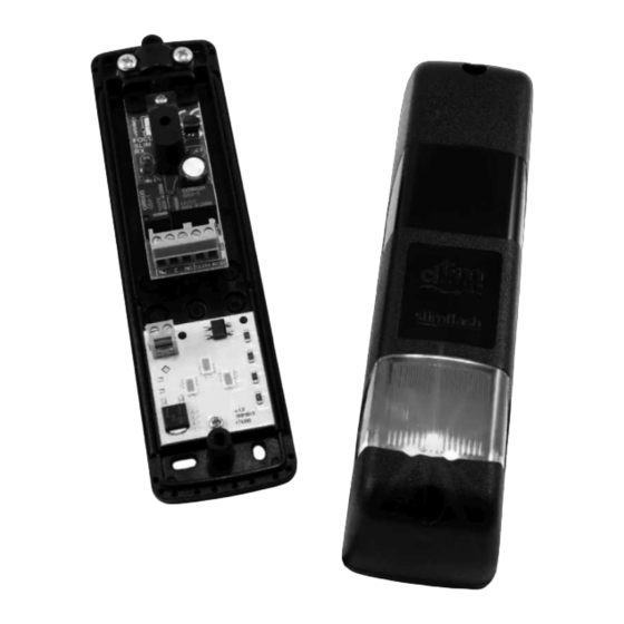
FOTOKOMÓRKA NATYNKOWA Z LAMPĄ
SYGNALIZACYJNĄ / OŚWIETLENIOWĄ
Instrukcja obsługi
A
UFPUTZ ICHTSCHRANKE
-L
MIT IGNAL
S
-/B
ELEUCHTUNGSLAMPE
Betriebsanleitung
PHOTOCELL WITH BUILT-IN
SIGNAL / LIGHTING LAMP
User's manual
v.4.0
PL
DE
EN
Advertisement

Summary of Contents for dtm slimflash
- Page 1 FOTOKOMÓRKA NATYNKOWA Z LAMPĄ SYGNALIZACYJNĄ / OŚWIETLENIOWĄ Instrukcja obsługi UFPUTZ ICHTSCHRANKE MIT IGNAL ELEUCHTUNGSLAMPE Betriebsanleitung PHOTOCELL WITH BUILT-IN SIGNAL / LIGHTING LAMP User’s manual www.dtm.pl...
- Page 3 • odporność lampy na wstrząsy i wibracje: wysoka • gabaryty zewnętrzne obudowy (szer. x głęb. x wys.): 38x36x145mm • sposób montażu: obudowa natynkowa, bryzgoszczelna, IP-54 • materiał obudowy: ABS, poliwęglanowe klosze (SLIMFLASH pomarańczowy SLIMFLASH B przejrzysty) • temperatura pracy (min./max.): -20°C / +55°C • waga: 165g...
- Page 4 3. Montaż fotokomórki i lamp sygnalizacyjnych / oświetleniowych 3.1. Montaż fotokomórki A b y f o t o k o m ó r k a d o b r z e funkcjonowała, nadajnik i odbiornik należy zamontować na wysokości 40 - 60 cm od ziemi. Odległość...
- Page 5 3.2.Zasady montażu lamp z funkcją sygnalizacyjną i oświetleniową Fotokomórka posiada wbudowane lampy LED, pełniące funkcję sygnalizacyjną w wersji z kloszem pomarańczowych lub funkcję oświetleniową w wersji z kloszem przejrzystym. Lampa sygnalizacyjna z kloszem pomarańczowym Lampa sygnalizacyjna spełnia swoje zadanie wtedy, gdy zamontowana jest w miejscu, z którego jest dobrze widoczna dla osób znajdujących się...
- Page 6 4. Podłączenie elektryczne fotokomórki Fotokomórka może współpracować z większością central sterujących automatyką bramową znajdujących się na rynku. Zaleca się, by instalację elektryczną i podłączenie P o d ł ą c z e n i e n a l e ż y fotokomórki wykonała osoba z odpowiednimi kwalifikacjami.
- Page 7 W przypadku problemów z identyfikacją przewodów zasilania AC, można posłużyć się poniższą procedurą, w celu prawidłowego podłączenia dwóch par fotokomórek znajdujących się w jednym obszarze zasięgu optycznego: • upewnić się, że zworki oznaczone ' ' w nadajnikach i w odbiornikach obu par fotokomórek są...
- Page 9 - TX LAMP NC C NO 12-24V LAMP 12-24V 12-24V AC/DC 12-24V AC/DC AC/DC AC/DC opisy zacisków funkcji oświetlenia zmierzchowego Elementy sugerowane przez DTM System przy wykorzystywaniu Rys. 5 Schemat elektryczny podłączenia lamp oświetleniowych fotokomórki do zasilacza i wyłącznika zmierzchowego.
- Page 10 7. Próby odbiorcze Po podłączeniu fotokomórki, należy dokonać testu, czyli sprawdzić reakcję odbiornika (RX) na przecięcie bariery świetlnej. Systemy automatyki bram muszą być testowane z uwzględnieniem normy PN-EN12445.Test pary fotokomórek: • podłączyć zasilanie tylko do odbiornika i sprawdzić czy dioda RX jest zgaszona. •...
- Page 11 38x36x145mm • Montageverfahren: Aufputzgehäuse Spritzwassergeschützt, IP-54 • Gehäusematerial: A B S , L a m p e n s c h i r m a u s Polycarbonat (SLIMFLASHOrange SLIMFLASH BTransparent) • Betriebstemperatur (min./max.): -20°C / +55°C • Gewicht: 165g...
- Page 12 3. Installation von Lichtschranken und Signal- /Beleuchtungslampen 3.1. Installation der Fotozelle Damit die Lichtschranke richtig funktioniert, sollten Sender und Empfänger in einer Höhe von 40 bis 60 cm über dem Boden montiert werden. Der Abstand zwischen Sender und Empfänger sollte nicht weniger als 1 m betragen.
- Page 13 3.2. Einbauvorschriften für Leuchten mitSignal- und Beleuchtungsfunktion Die Lichtschranke verfügt über eingebaute LED-Leuchten, die in der Version mit orangefarbenem Diffusor eine Signalfunktion und in der Version mit transparentem Diffusor eine Lichtfunktion haben. Signalleuchte mit orangefarbener Linse EineSignalleuchte erfüllt ihreAufgabe, wenn sie an einerStelle angebracht wird, von der aus sie für Personen im Betriebsbereich des Automatisierungssystems gut sichtbar ist.
- Page 14 4. ElektrischerAnschluss der Lichtschranke Die Lichtschranke kann mit den meisten auf dem Markt befindlichen Torautomationszentralen zusammenarbeiten. Es wird empfohlen, die elektrische Installation und den Anschluss der Lichtschranke von einer qualifizierten Person durchführen zu lassen. Der Anschluss erfolgt nach dem in Abb. 4 gezeigten Schema und nach der folgenden Beschreibung: Ohne Verwendung der Synchronisationsfunktion •...
- Page 15 Wenn Sie Probleme haben, die Wechselstromkabel zu identifizieren, können Sie das folgende Verfahren anwenden, um zwei Lichtschrankenpaare, die sich im gleichen optischen Bereich befinden, korrekt anzuschließen: • Vergewissern Sie sich, dass die mit " " gekennzeichneten Steckbrücken an den Sendern und Empfängern beider Lichtschrankenpaare gekreuzt (offen) sind;...
- Page 17 Empfänger - RX Sender - TX LAMP NC C NO 12-24V LAMP 12-24V 12-24V AC/DC 12-24V AC/DC AC/DC AC/DC Klemmleistenpläne Vom DTM-System vorgeschlagene Elemente bei Verwendung der Dämmerungslichtfunktion. Abb. 5 Elektrisches Anschluss-Schema der Fotozellen-Lampen an die Stromversorgung und den Dämmerungsschalter.
- Page 18 7. Empfangstests Nach dem Anschluss der Lichtschranke muss ein Test durchgeführt werden, d.h. die Reaktion des Empfängers (RX) auf das Überschreiten der Lichtschranke muss überprüft werden. Torautomatisierungssysteme müssen gemäß EN12445 geprüft werden. Test des Fotozellenpaares: • Schließen Sie die Stromversorgung nur an den Empfänger an und prüfen Sie, ob die RX- Diode ausgeschaltet ist.
- Page 19 • external dimensions of the housing (W x D x H): 38x36x145mm • mounting method: surface mounted housing, splash-proof, IP-54 • housing material: ABS, polycarbonate diffusers (SLIMFLASH orange SLIMFLASH B transparent) • working temperature (min./max.): -20 °C / + 55 °C • weight: 165g...
- Page 20 3. Installation of a photocell and signaling / lighting lamps 3.1. Installation of a photocell For the photocell to function properly, the transmitter and receiver should be installed 40 - 60 cm above the ground. The distance between the transmitter and the receiver should not be less than 1 m.
- Page 21 3.2. Principles of installation of lamps with signaling and lighting functions The photocell has built-in LED lamps that perform the signaling function in the version with an orange shade or the lighting function in the version with a transparent shade. Signal lamp with orange lampshade The signal lamp fulfills its task when it is installed in a place from which it is clearly visible to people in the automation work area.
- Page 22 4. Electrical connection of the photocell The photocell can work with the majority of gate automation control units available on the market. It is recommended that the electrical installation and connection of the photocell be performed by a suitably qualified person. The connection should be carried out in accordance with the diagram shown in and as described below: Fig.
- Page 23 In case of trouble identifying the AC power cables, to properly connect two pairs of photocells within one optical range the following procedure can be used: • make sure that the jumpers marked ' ' in the transmitters and receivers of both pairs of photocells are cut (open), •...
- Page 25 NC C NO 12-24V LAMP 12-24V 12-24V AC/DC 12-24V AC/DC AC/DC AC/DC terminal descriptions twilight lighting function Elements suggested by the DTM System when using the Fig. 5 Electrical diagram for connecting the photocell lighting lampsto the power supply and the twilight switch.
- Page 26 7.Acceptance tests After connecting the photocell, perform a test, i.e. check the receiver's (RX) reaction to the crossing of the light barrier. Gate automation systems must be tested in accordance with the PN-EN12445 standard. Photocell pair test: • connect the power supply to the receiver only and check that the RX diode is off. •...
-
Page 27: Warranty
EU Declaration of Konformitätsbestätigung ist unter zgodności UE jest dostępny pod Conformity is available at the unserWebsite zugänglich. adresem internetowym. Internet address. DTM System ul. Brzeska 7, 85-145 Bydgoszcz, Polska, tel. +48 52 340 15 83, www.dtm.pl... - Page 28 DTM System ul. Brzeska 7, 85-145 Bydgoszcz, Polska, tel. +48 52 340 15 83, www.dtm.pl...
Need help?
Do you have a question about the slimflash and is the answer not in the manual?
Questions and answers