
Summary of Contents for Et 400 Series
- Page 1 Erhardt + Leimer Inc. 350 Tucapau Road Duncan, SC 29334 USA Telephone 864/486-3000 Telefax 864/486-3011 BULLETIN 25 WEB GUIDING SYSTEMS B-25 Rev. 1/97...
- Page 2 NOTICE TO PERSONNEL Safety must be a primary concern for all personnel who operate, maintain, or service any of our machinery or its component parts. While we have tried hard to design our equipment to be as free from hazard as we feel we can reasonably make it, moving webs and automated equipment present safety hazards, which cannot always be completely eliminated through design.
-
Page 3: Table Of Contents
Bulletin 025 Web Guiding Systems TABLE OF CONTENTS SUBJECT PAGE I. SECTION DESCRIPTION AND OPERATION ..........1-3 ACTUATING DEVICES ............... 1 ACUTATION POWER ................. 1 WEBALIGNER POWER UNITS ............1 SENSING DEVICES................2 CONTROL OPTIONS ................2 DETAILED DESCRIPTION AND OPERATING INFORMATION..2-3 II. -
Page 4: Section Description And Operation
….E+L Bulletin 025, Web Guiding Systems SECTION I: DESCRIPTION AND OPERATION Whether simple or sophisticated, all web guiding systems contain the same basic components. They are listed below, by category, and are described in brief detail. Today's guiding systems find guiding components combined in many unusual and even unique ways, but they all have the same purpose, they control the web so that the web and the process retain the right relationship to one another. -
Page 5: Sensing Devices
….E+L Bulletin 025, Web Guiding Systems SENSING DEVICES Web guiding relies upon an integrated feedback control system; that is, the sensing device continuously senses web location and sends appropriate corrective signals to the actuating device. The control signal strength is dependent upon the position of the web and is, therefore, proportional. -
Page 6: Section Installation
….E+L Bulletin 025, Web Guiding Systems In other instances, notably in bulletins covering control options, you will be referred from one bulletin to another. In some cases, your web guiding system will be specially designed, and the accompanying instructions will be only generally applicable. In such cases, specific details will appear on the engineering drawings that accompany your order. -
Page 7: Control Option Interconnections
….E+L Bulletin 025, Web Guiding Systems Guiding Applications Chasing Applications Figure 1. System Interconnection 5. Run all tubing so that it will not kink or be pinched during operation, and so that it will not become entangled in the web or protrude into adjacent aisles. Pneumatic Tygon tubing must be run in gentle curves;... -
Page 8: Section Checkout
….E+L Bulletin 025, Web Guiding Systems SECTION III: CHECKOUT Checkout can be performed essentially on a component-by-component basis. Where system interconnection is involved, component checkout procedures define the interrelationship sufficiently to prove system operation. Because of the component interactions involved in a web guiding system, it is wise to complete all installation before proceeding with checkout. -
Page 9: Section Troubleshooting
….E+L Bulletin 025, Web Guiding Systems SECTION VI: TROUBLESHOOTING Most problems with web guiding equipment reveal themselves as system malfunctions. Consequently, all basic trouble-shooting is handled in the table below. Where specific maintenance or repair procedures must be followed, reference is made to the applicable bulletin. - Page 10 ….E+L Bulletin 025, Web Guiding Systems SYMPTOM CAUSES ISOLATING PROCEDURE REPAIR PROCEDURE Oil under power Hymod, oil Visually inspect unit to Replace leaking Hymod unit pump, or fittings determine source of oil; or oil pump; see Bulletin are leaking Disregard Spillage No.
- Page 11 ….E+L Bulletin 025, Web Guiding Systems SYMPTOM CAUSES ISOLATING PROCEDURE REPAIR PROCEDURE Noisy TRA or Bearing insert Check bar for rapid wear Replace bearing and adapter base has failed support bar; see Bulletin No. 400 Supporting knuckle Arcuate motion Shut down line; Move knuckle Repair cable of arcuate motion generator cable...
- Page 12 ….E+L Bulletin 025, Web Guiding Systems SYMPTOM CAUSES ISOLATING PROCEDURE REPAIR PROCEDURE System controls Light web Observe web edge within Install sole plate on inaccurately by material curls sensor sensor overreacting or under S1 overshooting pressure (continued) Servo cylinder Visually inspect Tighten retaining nuts mounting loose Cylinder...
- Page 13 ….E+L Bulletin 025, Web Guiding Systems SYMPTOM CAUSES ISOLATING PROCEDURE REPAIR PROCEDURE Guiding device 10 Micron outlet Loosen oil fittings slightly on Replace Hymod; see won’t move or only filter clogged top of Hymod and watch for Bulletin No. 100 moves sluggishly oil leakage;...
- Page 14 ….E+L Bulletin 025, Web Guiding Systems SYMPTOM CAUSES ISOLATING PROCEDURE REPAIR PROCEDURE Sensor and web Blower filter Remove belt guard at blower Clean or replace filter move apart clogged end of power unit; Visually suddenly inspect (continued) Tuft Aligner Visually inspect spring Replace spring installations: Tuft Aligner...
- Page 15 Erhardt + Leimer Inc. 350 Tucapau Road Duncan, SC 29334 USA Telephone 864/486-3000 Telefax 864/486-3011 BULLETIN 100 WEBALIGNER 400 SERIES POWER UNIT B-100 Rev. 1/97...
- Page 16 NOTICE TO PERSONNEL Safety must be a primary concern for all personnel who operate, maintain, or service any of our machinery or its component parts. While we have tried hard to design our equipment to be as free from hazard as we feel we can reasonably make it, moving webs and automated equipment present safety hazards, which cannot always be completely eliminated through design.
- Page 17 Bulletin 100 WebAligner Power Unit TABLE OF CONTENTS SUBJECT PAGE I. SECTION DESCRIPTION AND OPERATION ..........1-3 DESCRIPTION ..................1 OPERATION..................2 CONTROL OPTIONS ................3 II. SECTION INSTALLATION ................5-9 HANDLING ..................5 MOUNTING LOCATION..............5 CLEARANCES ..................5 ATTACHMENT ..................
- Page 18 Table of Figures Figure 1. WebAligner Power Unit, 400 Series Figure 2. Principles of Power Unit Operation Figure 3. Installation Clearances Figure 4. System Interconnection Figure 5. Exploded View of Power Unit Table of Tables Table 1. WebAligner Power Unit, 400 Series Table 2.
-
Page 19: Section Description And Operation
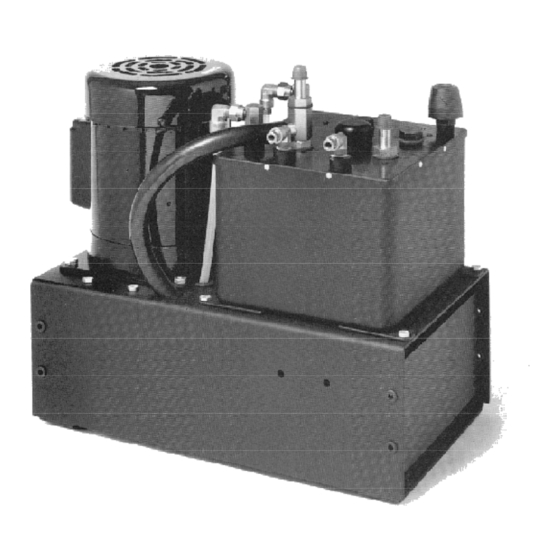
SECTION I: DESCRIPTION AND OPERATION DESCRIPTION The 400 Series WebAligner is a hydraulic power unit used in web guiding systems. Because it converts a pneumatic sensor signal directly into hydraulic output power, it acts as a pneumatic- hydraulic transducer-amplifier. Four models of the WebAligner exist. They provide varying working capacities and pressures to suit the needs of a wide range of applications. -
Page 20: Operation
10-micron filter located at the output of the pump. OPERATION The 400 Series WebAligner operates in conjunction with a pneumatic (fluidic) edge detector or similar device (described elsewhere in this instruction manual), which provides a proportional signal that varies in the range of 0.5 to 4.5 inches of water pressure. Signal pressure is varied by the position of the web being guided. -
Page 21: Control Options
0.015 inch or more. CONTROL OPTIONS The 400 Series WebAligner can be equipped with a number of control options. If your unit is so equipped, a full description of each option will be found in the 700 Series Bulletins in this... -
Page 22: Figure 2. Principles Of Power Unit Operation
….E+L Bulletin 100, WebAligner Power Units Figure 2. Principles of Power Unit Operation... -
Page 23: Section Installation
SECTION II: INSTALLATION HANDLING If handled with normal care, little can be done to damage the 400 Series WebAligner. However, when lifting the unit from its shipping container, do not use the wire-wound rubber hose running from the base to the top of the hydraulic module (Hymod) because you may pull it loose from its fittings. -
Page 24: Attachment
….E+L Bulletin 100, WebAligner Power Units Figure 3. Installation Clearances ATTACHMENT The unit should normally be bolted down when installed. The shipping bolts may be used for this purpose. Use a washer with a minimum O.D. of 0.750 inch between the bolt and rubber grommet in the bolt hole to prevent stripping the grommet from the hole. -
Page 25: Power Connection
….E+L Bulletin 100, WebAligner Power Units Table 2. Power Unit Installation Clearances Recommended Dimension* Reason Clearance Required Minimum 18” Permits changing of blower and belt. If unit is mounted from below, this dimension can be reduced to 6 inches. 6” Provides clearance for hoses and tubes. -
Page 26: Starters
….E+L Bulletin 100, WebAligner Power Units STARTERS: If the power unit is supplied with a starter, the motor and the starter are normally pre-wired at the factory. Connect the starter to your plant power supply. Install the heaters in the starter. Wiring diagrams and heater specifications are found within the starter box. When the power unit is part of a system containing a control panel, the starter is normally found within the panel. -
Page 27: Control Options And Detector Variations
….E+L Bulletin 100, WebAligner Power Units Figure 4. System Interconnection Do not use signal hose any longer than the 8-foot lengths supplied with your unit unless absolutely necessary. Increased length degrades accuracy of the signal. Run the signal hose in gentle curves;... -
Page 28: Section Checkout
….E+L Bulletin 100, WebAligner Power Units SECTION III: CHECKOUT Prepare and check out the power unit according to the following procedure, to see that it is ready to operate safely and reliably. Refer to the checkout procedures in the accompanying 300 Series and 700 Series bulletins to identify control and detector option settings that must be made prior to checkout. - Page 29 ….E+L Bulletin 100, WebAligner Power Units NOTE If the cylinder is mounted higher than the power unit, the above procedure will work only if the cylinder hydraulic fittings are loosened enough to permit some oil to bleed from them. This practice should be avoided whenever possible because it tends to create a mess unless the bleeding oil is closely confined and caught in a suitable container.
-
Page 30: Section Operating Instructions
Sunvis 816 WR SECTION IV: OPERATING INSTRUCTIONS There are no operating adjustments to be made on the 400 Series Power units. The units function entirely automatically, requiring only starting and stopping. Control option operating instructions are contained in the applicable 700 Series bulletin. -
Page 31: Breather/Dipstick
….E+L Bulletin 100, WebAligner Power Units BREATHER/DIPSTICK When checking the oil level, examine the fiber filter within the cap of the dipstick. If it becomes soaked with oil, the power unit will not operate properly. If it appears oil soaked, remove the Allen screw retaining the breather cap, install a new filter element, and replace the cap. -
Page 32: Section Repair
….E+L Bulletin 100, WebAligner Power Units SECTION VI: REPAIR REPLACING THE HYMOD Disconnect the 2 cylinder supply oil lines at the C-1 and C-2 ports. Label the lines for identification and cap them to prevent contamination. Disconnect the 2 oil lines from the right- angle fittings at the P and T ports. -
Page 33: Replacing The Motor Assembly
Disconnect the hydraulic lines from the pump assembly. Cap the lines to prevent contamination. Two pump mounting schemes are used in the 400 Series Power units: one version mounts the pump assembly on the "floor" of the base; the second version mounts the pump assembly beneath a bracket in the base. -
Page 34: Replacing The Timing Belt
….E+L Bulletin 100, WebAligner Power Units withdraw the remainder of the pump assembly from the base. If your version mounts on the floor, remove the 4 attaching bolts and withdraw the pump assembly from the base. If your replacement pump assembly is to be mounted on a bracket, loosen the set screws retaining the coupling, and remove the coupling and Woodruff key from the pump shaft. - Page 35 BULLETIN 100...
- Page 36 Erhardt + Leimer Inc. 350 Tucapau Road Duncan, SC 29334 USA Telephone 864/486-3000 Telefax 864/486-3011 BULLETIN 200 HYDRAULIC SERVO CYLINDERS B-200 Rev. 1/97...
- Page 37 NOTICE TO PERSONNEL Safety must be a primary concern for all personnel who operate, maintain, or service any of our machinery or its component parts. While we have tried hard to design our equipment to be as free from hazard as we feel we can reasonably make it, moving webs and automated equipment present safety hazards, which cannot always be completely eliminated through design.
- Page 38 Bulletin 200 Hydraulic Servo Cylinders TABLE OF CONTENTS SUBJECT PAGE I. SECTION DESCRIPTION AND OPERATION ............. 1 DESCRIPTION ..................1 OPERATION..................1 II. SECTION INSTALLATION ................2-4 HANDLING ..................2 MOUNTING ..................2-3 HYDRAULIC CONNECTION............... 4 III. SECTION CHECKOUT..................5-6 IV.
-
Page 39: Section Description And Operation
….E+L Bulletin 200, Hydraulic Servo Cylinders SECTION I: DESCRIPTION AND OPERATION DESCRIPTION The hydraulic servo cylinders found in E+L guiding systems provide the hydraulic power required to move a guiding device such as a Tracking Roller Assembly, a Steering Roller Assembly, or an Adapter Base. -
Page 40: Section Installation
MOUNTING Most hydraulic servo cylinders are already installed as a component of a guiding device when received. Mounting instructions for guiding devices are found in the 400 Series Bulletins in this instruction manual. The following guidelines pertain to cylinders newly mounted on existing equipment. - Page 41 ….E+L Bulletin 200, Hydraulic Servo Cylinders Table 2. Maximum Cylinder Force and Speed Cylinder Bore (Inches) Power Value Unit 1 ½ 2 ½ 3 ¼ Used 400B Force 1473 2490 3770 5890 Speed 1.30 0.67 0.41 0.25 0.16 600BE 400BM Force 1473 2490...
-
Page 42: Hydraulic Connection
….E+L Bulletin 200, Hydraulic Servo Cylinders Bore Stroke Length Dia. 1,1 ½, 2 11.375 12.875 14 75 15.87 17.37 18.8 21.8 2 ½ 11.500 13.000 14.500 16.000 17.500 19.000 22.000 25.000 28.000 34.000 3 ¼, 4 13.750 15.250 16.750 18.250 19.750 21.250 24.250... -
Page 43: Section Checkout
….E+L Bulletin 200, Hydraulic Servo Cylinders Guiding Application Chasing Application Figure 3. Interconnection of the Power Unit and the Cylinder SECTION III: CHECKOUT Prepar e and checkout the hydraulic servo cylinder according to the following procedure, to see that it i s ready to operate safely and reliably. - Page 44 It should reposition in the direction, which will move a web into the sensor. With 400 series power unit, if it repositions in the opposite direction, the hydraulic phasing of e power unit is incorrect. Shut down and switch the hydraulic lines at the power unit.
-
Page 45: Section Operating Instructions
….E+L Bulletin 200, Hydraulic Servo Cylinders SECTION IV: OPERATING INSTRUCTIONS The hydraulic servo cylinder functions entirely automatically during system operation. SECTION V: MAINTENANCE AND REPAIR E+L supplied hydraulic cylinders require no maintenance and only simple repair. It is uneconomical to perform any repairs oth er than the repla cement of seal members and fittings. - Page 46 Erhardt + Leimer Inc. 350 Tucapau Road Duncan, SC 29334 USA Telephone 864/486-3000 Telefax 864/486-3011 BULLETIN 300 PNEUMATIC SENSORS B-300 Rev. 1/97...
- Page 47 NOTICE TO PERSONNEL Safety must be a primary concern for all personnel who operate, maintain, or service any of our machinery or its component parts. While we have tried hard to design our equipment to be as free from hazard as we feel we can reasonably make it, moving webs and automated equipment present safety hazards, which cannot always be completely eliminated through design.
- Page 48 Bulletin 300 Pneumatic Sensors TABLE OF CONTENTS SUBJECT PAGE I. SECTION DESCRIPTION AND OPERATION ..........1-4 DESCRIPTION ..................1 OPERATION..................1-4 II. SECTION INSTALLATION ................5-7 PNEUMATIC SENSORS ..............6 POROUS SENSING OR THREE LEG SENSORS......7 III. SECTION CHECKOUT ..................8-9 CHECKING THE AIR JETS..............
-
Page 49: Section Description And Operation
….E+L Bulletin 300, Pneumatic Sensors SECTION I: DESCRIPTION AND OPERATION DESCRIPTION Pneumatic sensors sense the true web side lay position in web processes, and establish the process pass line. They consist of a "U"-shaped assembly (Figure 1) through which the web passes. - Page 50 ….E+L Bulletin 300, Pneumatic Sensors WITH FLAPPER SMALL CONFIGURATION SPECIAL AIR SUPPLY THREE LEG EXTENDED LEG POROUS MATERIAL Figure 2. Specialized Sensors S1 restricts the flow of air from S2. S2 pressure is at its highest Figure 3. Pressure Conditions with No Web in Place Each finger contains an orifice, both of which are out breathing.
- Page 51 ….E+L Bulletin 300, Pneumatic Sensors S1 restricts half of the air from S2. S2 pressure level causes no corrective action. Scribed line identifies the process pass line. Figure 4. Pressure Conditions, Web in Desired Position S1 restricts more than half of the air from S2. S2 pressure level rises (from level in Figure 4) and causes corrective action to move the web back into the throat.
- Page 52 ….E+L Bulletin 300, Pneumatic Sensors Figures 3, 4, 5, and 6 illustrate the conditions found in the sensor during operation. Figure 3 shows the sensor with no web in place. The relative length of the exhaust air lines on the drawings approximate the flow of air.
-
Page 53: Section Installation
….E+L Bulletin 300, Pneumatic Sensors SECTION II: INSTALLATION PNEUMATIC SENSORS If your sensor has not been factory installed on your equipment prior to shipment, install it according to the following parameters: 1. The sensor must be mounted rigidly; movement of the sensor during operation can affect accuracy of your system. - Page 54 ….E+L Bulletin 300, Pneumatic Sensors 6. If the sensor is used in conjunction with a TRA equipped with a pneumatic passline follower, mount the sensor on the follower, which compensates for web passline fluctuation at extreme corrections. 7. If the sensor is used in conjunction with a TRA with a large correction range and no passline follower is available, the web passline may fluctuate beyond the width of the sensor throat.
-
Page 55: Porous Sensing Or Three Leg Sensors
….E+L Bulletin 300, Pneumatic Sensors POROUS SENSING OR THREE LEG SENSORS If you are installing a porous sensing or three-leg sensor, install it according to the parameters given below. Figure 9 shows sensor interconnection. Figure 9. Interconnection of Three Leg Sensors 1. -
Page 56: Section Checkout
….E+L Bulletin 300, Pneumatic Sensors SECTION III: CHECKOUT CHECKING THE AIR JETS Start the power unit. Check both the S1 and S2 jets to see that air is flowing freely from them both. If one jet appears to be obstructed, check the air lines for kinks and disconnect the line supplying the problem jet. -
Page 57: Section Operating Instructions
….E+L Bulletin 300, Pneumatic Sensors 3. Turn on the shop air gradually while moving a playing card in and out between the shop air port and the Sl port. As shop air begins to modulate the Sl exhaust, the actuator will move in an erratic fashion in one direction. Continue to turn up the shop air until the actuator operates smoothly, and then increase the air pressure 1/4 PSI. -
Page 58: Porous Material Sensors
….E+L Bulletin 300, Pneumatic Sensors POROUS MATERIAL SENSORS When running a porous material with a large, open mesh, move the web into and out of the sensor quickly during set-up. When changing back and forth between large, open mesh webs and solid webs (or webs with a small tight mesh), it may be necessary to readjust the air pressure regulator to achieve operation. - Page 59 Erhardt + Leimer Inc. 350 Tucapau Road Duncan, SC 29334 USA Telephone 864/486-3000 Telefax 864/486-3011 BULLETIN 325 VERNIER ADJUSTING BRACKET B-325 Rev. 1/97...
- Page 60 NOTICE TO PERSONNEL Safety must be a primary concern for all personnel who operate, maintain, or service any of our machinery or its component parts. While we have tried hard to design our equipment to be as free from hazard as we feel we can reasonably make it, moving webs and automated equipment present safety hazards, which cannot always be completely eliminated through design.
- Page 61 Bulletin 325 Vernier Adjusting Bracket TABLE OF CONTENTS SUBJECT PAGE I. SECTION DESCRIPTION ..................1 II. SECTION INSTALLATION .................. 1 III. SECTION OPERATING INSTRUCTIONS ............2 SETUP....................2 ADJUSTMENT DURING OPERATION ..........2 IV. SECTION MAINTENANCE AND REPAIR............2...
- Page 62 ….E+L Bulletin 325, Vernier Adjusting Bracket SECTION I: DESCRIPTION DESCRIPTION AND OPERATION The Vernier Adjusting Bracket consists of two adjustable arms, one capable of mounting on a support bar and the other containing a fine-thread adjusting mechanism. The purpose of the device is two-fold.
- Page 63 ….E+L Bulletin 325, Vernier Adjusting Bracket Mount the edge sensor on the square end of the vernier adjusting mechanism. A 1/4-20 bolt, nut, washer, and stand-off are provided for this purpose. (Two other holes, one tapped, provide alternate sensor mounting locations.) Turn the adjusting knob on the vernier mechanism to see that it turns freely.
Need help?
Do you have a question about the 400 Series and is the answer not in the manual?
Questions and answers