Table of Contents

Related Manuals for Silent Sentinel Jaeger

Summary of Contents for Silent Sentinel Jaeger
- Page 1 SILENT SENTINEL ARE SPECIALISTS IN LONG RANGE JAEGER INSTALLATION GUIDE OPTICAL SENSORS INCLUDING BOTH COOLED AND UNCOOLED THERMAL CAMERAS Silent Sentinel Jaeger Mechincal Installation Guide Version: V1.0 Date: 06/08/2021 Commercial in Confidence 1/26...
- Page 2 We try our best to make sure all the contents in this manual are accurate. We do not provide any representations or warranties in this manual. If you need the latest version of this manual, please contact us. Silent Sentinel recommends that you use this manual under the guidance of professionals.
-
Page 3: Table Of Contents
System Orientation ............................5 Mechanical Installation ............................6 Overview ................................ 7 Fixtures and Fittings; ............................7 Mouting the Jaeger PTU ..........................8 Attaching the Top Mount ..........................9 Attaching the Side Payloads ........................10 Wiper Assembly Installation ..........................12 Overview ..............................12 Fixtures and Fittings ............................. - Page 4 JAEGER INSTALLATION GUIDE INSTALLATION SHOULD BE CARRIED OUT BY QUALIFIED PERSONNEL ONLY IN ACCORDANCE WITH THE APPLICABLE LOCAL CODES. THE MANUFACTURER CAN ACCEPT NO LIABILITY FOR ANY DAMAGES OR LOSSES CAUSED DUE TO INCORRECT OR IMPROPER INSTALLATION. Safety Information Before installing the equipment, please read this guide carefully.
-
Page 5: System Overview
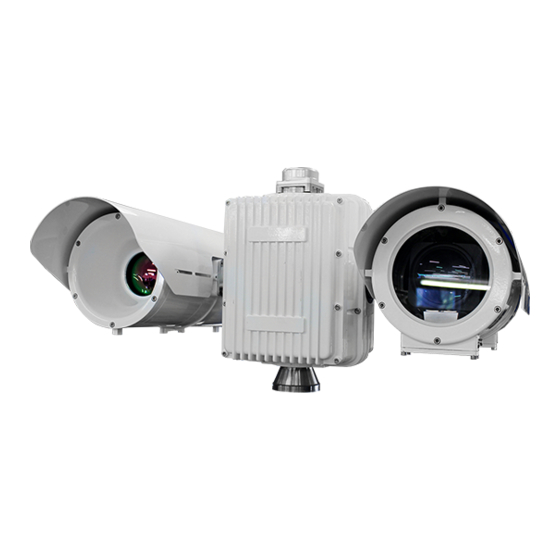
Figure 2 The image on the top left (Figure 1) shows a ‘MK2’ Jaeger with the additional spacer fitted. This spacer can be used to identify the ‘Back’ and ‘Front’ of the PT Unit. If you face the rear of the unit,... - Page 6 ADDITIONAL / DIFFERING MODULES BE USED. ALWAYS CONSULT THE TEST REPORTS DELIVERED WITH THE UNIT. DEPENING ON THE MODULES PROVIDED THE INSTALLATION LOCATIONS MAY ALSO VARY. IF THE SYSTEM HAS MORE THAN TWO PAYLOADS PLEASE REFER TO SILENT SENTINEL FOR GUIDANCE. Commercial in Confidence 6/26...
-
Page 7: Mechanical Installation
4. Cable / PSU Note: The system should not be powered on when any of the payloads / top mounts are attached. Fixtures and Fittings; The followings fittings are providing with the Jaeger System. Figure 3 Jaeger Fittings 1. Sun Shield Fixings;... -
Page 8: Mouting The Jaeger Ptu
JAEGER INSTALLATION GUIDE Mouting the Jaeger PTU Step Detail The image on the right shows the Jaeger mouting points. Line up the Jaeger Pedestal with the mast. Attached using the provided Fixings. Commercial in Confidence 8/26... -
Page 9: Attaching The Top Mount
JAEGER INSTALLATION GUIDE Attaching the Top Mount Step Detail The image on the right shows the Jaeger Top Mount connector and highlights the locating pins. Line up the provided top mount with the locating pins and attach using the provided fixings. -
Page 10: Attaching The Side Payloads
JAEGER INSTALLATION GUIDE Attaching the Side Payloads Note: please ensure you are attaching the payloads to the correct side. Please refer to the Ssytem Overview section for further information. Step Detail Protective caps are fitted to the ends of the shafts to prevent moisture and impact damage to the electrical connections. - Page 11 JAEGER INSTALLATION GUIDE Once the tube is fully located on the shaft the top securing screw should be inserted and partially tightened – not all the way. The remaining two screws should be inserted in to their respective holes and, once in place, all three...
-
Page 12: Wiper Assembly Installation
JAEGER INSTALLATION GUIDE Wiper Assembly Installation Overview This guide details the steps involved to install the wiper assembly onto a RHT camera housing. Fixtures and Fittings 1. Wiper Assembly 2. Wiper Blade 3. O-Ring 4. Fixings Step Detail Power down the camera unit and remove the bottom cover at the front of the camera housing. - Page 13 JAEGER INSTALLATION GUIDE Insert the supplied O-Ring into the groove on the wiper box. Align the wiper assembly holes with camera house jack plug holes Screw the supplied M4x 50 screws into the QTY4 fixing holes. Ensure that the O’ring is seated properly when screwing together Insert the spring into the wiper assembely shaft.
- Page 14 JAEGER INSTALLATION GUIDE Fit the wiper onto the shaft, locate the wiper at the desired park position and tighten. Note: the wiper ‘wipes’ anti-clockwise as you look at the face of the tube. Therefore, the park position should be to the right of the window and outside of the FOV of the camera.
- Page 15 Boresight Guide Overview As standard Silent Sentinel factory boresights the cameras ‘paralell’ at full tele. Therefore, the separate between FOV should never be any greater than the seperation of the payloads. However, should it be desired the boresight postion can be adjusted externally as detailed below.
- Page 16 JAEGER INSTALLATION GUIDE Vertical Adjustment Step Detail The cover is secured by four screws requiring an M3 Allen key tool. Using an M3 Allen key, loosen (do not remove) the locking screw that is located beside the adjustment wheel. The vertical action can now be made by turning the adjustment wheel using a chisel-tip (slot) screw driver.
- Page 17 JAEGER INSTALLATION GUIDE ANNEX 1 – Galvanic Kit Galvanic Kit Provided with the Galvanic Kit: 1. 4 x M8x20 aluminium bolts 2. Rubber matting for underneath base 3. Aluminium lanyard 4. 4x Nylon Shoulder Washers The galvanic kit prevents galvanic corrosion from happening on the base on the unit. It isolates the metal of the unit from the metal of the mast or platform it’s secured on.
-
Page 18: Cable Information
JAEGER INSTALLATION GUIDE ANNEX 2 - Cable Information Cable Overview The JCM cable supplied with the Jaeger can come in various lengths (up to 50m) and in two different formats; 1. Double ended; a. Each end of the Jaeger cable is terminated with a MIL38K Connector i. -
Page 19: Physical Connectors
JAEGER INSTALLATION GUIDE ANNEX 3 - Physical Connectors Jaeger Base Connector IL38K Amphenol TV-Series/ (D38999 ). Base Socket: Amphenol TVP00ZN21-29P Cable Connector: Amphenol TV06ZN-21-29SN Contact arrangement: 21-29. Contacts No.20 and No.25 are Coaxial types for Video transmission. View in to Socket face. -
Page 20: Side Payload Mounting Connector
JAEGER INSTALLATION GUIDE Side Payload Mounting Connector. MIL-D38999 G39 Amphenol D38999 Series-III / TV. PTZ Hub Socket: Amphenol D38999/20FG39SN (Connector on payload: Amphenol D38999/26FG39PN – For attached equipment) Contact arrangement: G39 / 21-99 - [G39T]. Contact “r” is a Coaxial type for Video transmission on HD-SDI models. -
Page 21: Top Payload Mounting Connector
JAEGER INSTALLATION GUIDE Top Payload Mounting Connector. MIL-D38999 G39 Amphenol D38999 Series-III / TV. Top Mounting Socket: Amphenol D38999/20FG39SN (Connector on payload: Amphenol D38999/26FG39PN – For attached equipment) Contact arrangement: G39 / 21-99 - [G39A]. Connections pass through directly to base connector.
Need help?
Do you have a question about the Jaeger and is the answer not in the manual?
Questions and answers