
Summary of Contents for STS 1600
- Page 1 1600 Automatic Shaker Unit Installation, Operations & Maintenance Manual S/N: Rev.: 2.0...
- Page 2 When you need service or technical help, please let us know your purchase invoice number. This will make it easier to provide you with correct service. For your convenience, space is provided below for you to record your local STS service contact information.
- Page 3 Rev. 2.0 General 1. General Carefully read the instructions in this manual as they contain important information re- garding proper, efficient and safe installation, use and maintenance of the unit. The installation of this unit must be carried out in accordance with the manufacturer’s instructions.
-
Page 4: Safe Use Of The Appliance
For your safety. Do not store or use gasoline or other flammable vapors or liquids in the vicinity of this or any other appliance. 2.2 Other prohibitions (dangerous procedures) Using any parts other than genuine STS approved manufactured parts can void the warranty. Improper installation, adjustment, alteration, service or maintenance can cause property damage or major injury. -
Page 5: Functional Description
Rev. 2.0 Functional description 3. Functional description 3.1 General Model 1600 shakers are: • Electrically heated Heated by infrared tubes • Have both auto/manual interface • Mesh belt driven • • Electronically controlled Automatically sensor controlled •... - Page 6 Rev. 2.0 3.2.1 Component Locations Powder box switch Multifunction relay PLC touch screen Powder recycle drawer Manual switch Powder box Maintenance note* Keep powder box free from debris that mixes in with TPU powders. Brush unwanted material from powder box area daily and remove unwanted debris from recycle bin before reuse into powder box.
- Page 7 Rev. 2.0 1. Powder blocking strip (under front top cover) 1. Vented oven lid 2. Vacuum cooling cylinder 3. Cooling fans 4. Motorized take-up reel...
- Page 8 Maintenance note* With the vented oven lid in the open position and the unit unplugged, fix the lid in place using the securing arm. Then using a dry paper towel..remove any oily residue from surfaces inside the heating chamber every week. Also wipe the interior of the two-zone filtration system and housings by opening...
- Page 9 Rev. 2.0 Maintenance note* The two-zone HEPA and charcoal filters should be replaced as needed. With regular use each filter lasts approximately 3-4 months. To remove and replace filters, unscrew interior locking nuts (black tops) and slide each filter upward to remove. Do the opposite to replace then affix door and seal with key locks.
- Page 10 Rev. 2.0 Mesh guide belt Maintenance note* Always remove any unwanted material from the recycled powder tray upon inspection. TPU powder should be completely white and sediment-free. Recycled powder tray...
- Page 11 Maintenance note* After each daily workflow using 2000 grit sandpaper, gently sand across the vacuum cylinder to remove any surface buildup which may have occurred. This will ensure proper gripping of the PET film through the system. Vacuum cylinder...
-
Page 12: Before Using The Unit
You will produce better re-sults if you understand the technology and follow the “rules”. 4. 2 The STS 1600 operates in both automatic and manual modes as selected by the user on the PLC touch screen. (1) & (2) The automatic/manual modes control the complete operation of the STS 1600. - Page 13 Rev. 2.0 (11) IO allows the user to enter the monitoring interface (12) Para set allows the user to enter the parameters settings Monitoring Interface (1) X0 denotes the operation of the sensor under the preheating platform stays white when it senses media feeding, and turns red when it does not sense media.
- Page 14 Rev. 2.0 (1) Dusting induction is set with a timing alarm that sounds after the powder spreading time is reached (2) Heating delay sets the heating delay time when the heating function is in the off position, time can be extended according to the new set time (3) Heat temperature of the infrared heating tunnel is set according to the melting temperature of the adhesive powder (4) Shaking strength adjusts the shaking strength of the powder removal sequence...
- Page 15 Rev. 2.0 After finishing the current print job, cut the last part of PET media and enter the print linkage mode. The film will then be automatically wound by the take-up to complete the printing process. Recycling the hot melt powder is accomplished simply by brushing the powder from the interior walls into the recycled powder tray (pg.7) and refill it into the powder box (pg.
- Page 16 Rev. 2.0 Electrical Terminal1(T1) Number Connect Location T1-A1 C1-3/L2, C1-5/L3 T1-B1 C1-L1 T1-C1 T2-E1 AC contactor(C1) Number Connect Location C1-A1 C1-1/L1 C1-1/L1 T1-B1 C1-2/T1 T2-I1,T2-J1 C1-3/L2 T1-A1 C1-4/T2 T2-K1 C1-A2 T4-J1 C1-5/L3 T1-A1,T4-I1 C1-6/T3 T2-L1...
- Page 17 Rev. 2.0 Terminal2(T2) Number Connect Location T2-E1 T1-C1,T1-C1 T2-F1 Y12-2 T2-G1 T2-J1 T2-H1 DA-Y10-2 T2-I1 C1-2/T1 T2-J1 C1-2/T1,T2-G1 T2-K1 C1-4/T2 T2-L1 C1-6/T3 T2-A2 Paper sensor,PLC-X03 T2-B2 Paper sensor,P1-V+1 T2-C2 Paper sensor,Blower connector1,Blower connector2,P1-G3 T2-D2 Blower connector1,Blower connector2,Y10-2 T2-E2 P1-FG,P2-FG,Blower Earth,Paper roller Earth T2-I2 Quick Connector ,T3-B2,P2-IN T2-J2...
- Page 18 Rev. 2.0 Power(P1) Number Connect Location P1-AC Y12-1,T2-J2 P1-IN T2-J2 P1-FG P1-FG Suction connector P1-G3 T2-C2, P1-G2 PLC-COM,T4-E1,PLC-COM6,PLC-COM4 P1-G1 T3-C2,PLC-0V P1-V+3 T3-D2,PLC-24V P1-V+2 Y6-3,Y12-3,Y10-1,Y7-1 P1-V+1 T2-B2,T4-D1...
- Page 19 Rev. 2.0 Terminal3(T3) Number Connect Location T3-A1 Heating Lamp-Naught wire T3-B1 Heating Lamp-Naught wire T3-C1 Aiifar 4c step_moto_V1---V- T3-D1 Y5-3,Aiifar 4c step_moto_V1---V+ T3-A2 T2-J2 T3-B2 T2-I2 T3-C2 P1-G1 T3-D2 P1-V+3...
- Page 20 Rev. 2.0 Terminal4(T4) Number Connect Location T4-A1 Warm-up T4-B1 Warm-up T4-C1 PLC-X00 T4-D1 P1-V+1 T4-E1 P1-G2 T4-F1 PLC----+/- T4-G1 PLC----+/- T4-H1 Not connect T4-I1 C1-5/L3 T4-J1 C1-A2 T4-K1 Y11-1 T4-L1 T2-J2 Number Connect Temperature control T4-A2 Temperature control T4-B2 T4-C2 Paper Feed Signal T4-D2 Paper Feeding V+,PotentiometerV+...
- Page 21 Rev. 2.0 Number Connect Location PLC- Not connect COMO PLC-Y4 Not connect PLC- PLC-COM2 COM1 PLC-Y5 Y5-4 PLC- PLC-COM1 COM2 PLC-Y6 Y6-4 PLC- PLC-COM4 COM3 PLC-Y7 Y7-4 PLC- PLC-COM3,P1-G2 COM4...
- Page 22 Rev. 2.0 PLC-Y10 DA-Y10-4 PLC-Y11 Y11-4 PLC-Y12 Y12-4 PLC- PLC-COM6 COM5 PLC-Y13 Y13-4 PLC-Y14 PLC-Y16 PLC-Y15 Not connect PLC- PLC-COM5,P1-G2 COM6 PLC-Y16 PLC-Y14 PLC-Y17 Y17-4 PLC- P1-V+3 PLC-0V P1-G1 PLC- Not connect PLC- P1-G2 PLC- T4-C1 PLC-X01 Not connect PLC-X02 Not connect PLC-X03 T2-A2...
- Page 23 Rev. 2.0 Relay:sunction Y7 Connection Location Y7-1 P1-V+2 Y7-2 Suction connector 10-DD Suction Y7 Y7-3 Y10-3 Y7-4 PLC-Y7 Relay:Blow Y10 Connection Location P1-V+2 Y10-1 10-DD Blow Y10 T2-D2 Y10-2 Y12-3,Y7-3 Y10-3 Relay:Paper Y12 PLC-Y10 Connection Location Y10-4 Y12-1 P1-AC,Y11-2 Y12-2 T2-F1 Y12-3 Y10-3,P1-V+2...
- Page 24 Rev. 2.0 Y11-1 T4-K1 Y11-2 DA-Y10-1 Y11-3 Y13-3,Y16-3 10-DA Dehumidification Y11 Y11-4 PLC-Y11 Relay:Drying Y17 Connection Location Y17-1 T2-L2 Y17-2 Quick Connector 10-DA Drying Y17 Y17-3 Y16-3,Y6-3 Y17-4 PLC-Y17 Relay:Heating Y13 Connection Location Y13-1 Y16-1 Live Wire Y13-2 Heating Lamp-- 10-DA Heating Y13 Y13-3 DA-Y10-3,Y11-3...
- Page 25 Rev. 2.0 Connection Location Live Wire Y14-1 Heating Lamp-- Y14-2 T2-L2 40-DA Heating Y14 Y14-3 Y5-3 Y14-4 PLC-Y14 Relay:Smoke removal Y5 Connection Location Y5-1 Smoke removal device Y5-2 Y16-1 10-DA Smoke removal Y5 Y5-3 Y14-3,T3-D1 Y5-4 PLC-Y5 Power2(P2) Power INPUT:88-132VAC 3.0A 176-264VAC 1.5A OUTPUT:+41V-3.0A 47-63HZ...
- Page 26 Rev. 2.0 P2-IN T2-I2 P2-FG T2-E2 P2-G Not connect Microstep Drive(MD) Number Connect Location P2-V+ P2-V- ENA- PLC-Dedusting ENA+ DIR+ DIR- PLC-Dedusting DIR+ ENA+,PUL+ PUL- PLC-Dedusting PUL+ DIR+,PLC-Dedusting...
- Page 27 Rev. 2.0 Microstep dirve ENA- ENA+ DIR- DIR+ PUL- PUL+...
- Page 28 Rev. 2.0 Number Connect Location T4-I2 Emergency switch-C Number Connect Location Rotary Switch-B T4-J2 Quick Connector...
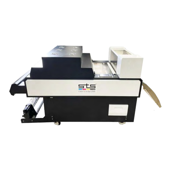
- Page 29 Rev. 2.0 Positioning the unit The STS 1600 Shaker unit dimensions are: 5.24 ft length 2.95 ft width 3.80 ft height Electrical connections cable 12-220v single phase 30 AMP...
Need help?
Do you have a question about the 1600 and is the answer not in the manual?
Questions and answers