Table of Contents
Advertisement
Advertisement
Table of Contents

Related Manuals for iXBlue OCTANS


Summary of Contents for iXBlue OCTANS
- Page 1 OCTANS generation User Manual...
- Page 3 OCTANS – User Manual Document Revision History Edition Date Comments 03/2015 First Edition 04/2015 Certification chapter updated. Repeater connector pinout updated. 09/2015 Certification and outputs sections updated 11/2015 Mechanical figure updated MU-OCTANS-AN-020 Ed. D – November 2015...
- Page 4 improvements.
- Page 5 The Warning icon indicates that possible personal injury or death could result from failure to follow the provided recommendation. Abbreviations and Acronyms Abbreviations and acronyms are described in the document Inertial Products - Principle & Conventions (Ref.: MU-INS&AHRS-AN-003). MU-OCTANS-AN-020 Ed. D – November 2015...
-
Page 6: Table Of Contents
Definition of the 4 Pulse Inputs and 2 Pulse Outputs ............21 6.6.5 Definition of the Configuration and Repeater I/O Signal ............ 22 ......................23 THERNET ONNECTOR ......................24 ECOMMENDED IRINGS OCTANS & PC ..........27 PECIFICATIONS FOR OMMUNICATION BETWEEN MU-OCTANS-AN-020 Ed. D – November 2015... -
Page 7: Introduction
(COG) of the vehicle/vessel. In this case, OCTANS will compute heave at the COG and add the heave induced by lever arms from the COG to external monitoring points. For more details see: •... -
Page 8: Product Documentation
OCTANS – User Manual RODUCT OCUMENTATION Your OCTANS belongs to the family of the iXBlue inertial products. The following documents are useful to use the best way your product. • This OCTANS User Manual gives information about: Mechanical Specifications ... - Page 9 Inertial Products – Application Note – Installation and Configuration of AHRS and INS for Seabed Mapping Measurements (Ref.: MU-HEAVAPN-AN-001) Inertial Products – Application Note – Mechanical Integration of Inertial Systems (Ref.: MU-MECHAPN-AN-001) MU-OCTANS-AN-020 Ed. D – November 2015...
-
Page 10: Verification Of Pack Contents
ONTENTS You will find in the shipping case a Packing List detailing all the items delivered. This Packing List has been completed and checked by iXBlue before shipment, and should match the contents of the pack you have received. However, we recommend checking the contents of the pack with the packing list document immediately after reception. -
Page 11: Certification
For products compliant with the « European marine equipment directive » (MED), please, note that: • MED certificates are available on iXBlue website. • This product category is « protected from the weather » (according to IEC 60945 §4.4 and to IMO resolution A694/5). -
Page 12: Mechanical Specifications
P, which is defined in Figure 2. Measurements can be performed at an external monitoring point. The position of this point has to be measured with respect to OCTANS center of measurement and entered in the OCTANS Configuration through the Web-based User Interface. - Page 13 OCTANS – User Manual Figure 1 - OCTANS dimensions MU-OCTANS-AN-020 Ed. D - November 2015...
- Page 14 OCTANS – User Manual Figure 2 - OCTANS Center of Measurement MU-OCTANS-AN-020 Ed. D - November 2015...
-
Page 15: Electrical Interface Specification
OCTANS – User Manual LECTRICAL NTERFACE PECIFICATION General Overview OCTANS electrical interface is fully compatible with previous OCTANS generation. 6.1.1 UTPUTS • Serial: 3 independent and configurable digital outputs (A,B,C) to be selected from a complete set of existing protocols (refer to document AHRS-Interface Library (Ref.: MU-AHRS-AN-003), with RS232 or RS422 levels. -
Page 16: Inputs
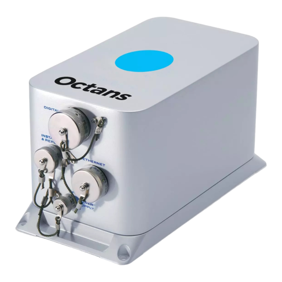
4 inputs flow for the external sensors Description of the Connector Panel All OCTANS inputs/outputs are made via four sealed connectors. The connector panel of the OCTANS unit holding these connectors is shown in Figure 3. The connector are Amphenol Socapex ones. -
Page 17: Listing Of Interfaces
• 2 inputs/5 outputs user-configurable through the Ethernet connector described in section 6.7 I/O interfaces can be user configured. This is done with the Web-based User Interface embedded into OCTANS. For detail, refer to Inertial Products - Web-based Interface User Guide (Ref.: MU-INSIII-AN-021). MU-OCTANS-AN-020 Ed. D - November 2015... -
Page 18: Power Supply Connector
OCTANS is powered directly in 24VDC by a specific power supply different from the one provided by iXBlue. OCTANS does not possess an on/off switch. As soon as it is powered, it begins to seek geographical North. Any interruption of the power supply, even brief, will return the system to its initial condition and it will begin to seek North again. -
Page 19: Repeater And Configuration Connector
OCTANS – User Manual Repeater and Configuration Connector This connector is used for configuring OCTANS and / or to display data using the Web- based User Interface when connection through the Ethernet one is not possible. Refer to Inertial Products - Web-based Interface User Guide (Ref.: MU-INSIII-AN-021) for detail on the software. -
Page 20: Digital Connector
User Guide (Ref.: MU-INSIII-AN-021) for detail. They are used: • For connection of external sensors to OCTANS: connecting a GPS or a log to a serial input, connecting a log sensor to a pulse input to get respectively external input of latitude and speed into OCTANS •... - Page 21 GND_R for repeater port). Serial GND pins are insulated from each other (i.e., GND_A is insulated from GND_B) and from power supplies GND and mechanical one (housing). Mechanical ground (pin t) Figure 4 - Diagram of the digital I/O connector MU-OCTANS-AN-020 Ed. D - November 2015...
-
Page 22: Definition Of The 2 Inputs And 3 Outputs In Rs232 Format
Table 10 - Pin assignment for the three digital outputs in RS 422 format RS 422 Ground Signal + Signal - Output A pin A pin B pin C Output B pin D pin E pin F Output C pin G pin H pin J MU-OCTANS-AN-020 Ed. D - November 2015... -
Page 23: Definition Of The 4 Pulse Inputs And 2 Pulse Outputs
AHRS - Interface Library (Ref.: MU-AHRS-AN-003) for further detail on the pulse input requirements. The pulse outputs deliver TLL 0 to +5 V signal with an output that can drive a maximum current of 1 mA. MU-OCTANS-AN-020 Ed. D - November 2015... -
Page 24: Definition Of The Configuration And Repeater I/O Signal
PC TX Shield Shield (*): If you are using your cable for both OCTANS latest generations and OCTANS III, it is recommended connect this pin as well. Caution The configuration and repeater I/O available on the Digital connector is internally connected to the configuration and repeater I/O available on the dedicated Installation and Repeater Connector (see section 6.5). -
Page 25: Ethernet Connector
RJ45. It offers an Ethernet Class D/Cat 5e connection for 10 Base T or 100 Base TX networks. Refer to Figure 5 for the corresponding wiring. The reference of the plug to be connected on the Ethernet connector on the OCTANS unit is AMPHENOL SOCAPEX RJF6MN. -
Page 26: Recommended Wirings
All pins marked GND are common electrical ground and can be used indifferently. Mechanical GND connection is recommended through connector backshell or Pin t on Digital I/O Figure 7 - Description of mono-directional RS232 Input wiring (Port A example) MU-OCTANS-AN-020 Ed. D - November 2015... - Page 27 All pins marked GND are common electrical ground and can be used indifferently. Mechanical GND connection is recommended through connector backshell or Pin t on Digital I/O Figure 9 - Description of the RS422 Output wiring with a Shielded Twisted Pair (Port A example) MU-OCTANS-AN-020 Ed. D - November 2015...
- Page 28 All pins marked GND are common electrical ground and can be used indifferently. Mechanical GND connection is recommended through connector backshell or Pin t on Digital I/O Figure 12 - Description of the Pulse Input wiring with a Shielded Twisted Pair (Port A example) MU-OCTANS-AN-020 Ed. D - November 2015...
-
Page 29: Specifications For Communication Between Octans & Pc
Web-based User Interface (see Network Set-up Guide (Ref.: MU-INS&AHRS-AN-005) for more details). For the Ethernet link, the following parameters are default defined: • IP Address: 192.168.36.1xx, xx being the last two numbers of the OCTANS serial number • Connection through http web server (port 80) •...
Need help?
Do you have a question about the OCTANS and is the answer not in the manual?
Questions and answers