Advertisement
Genus™ WiFi Installation
Introduction
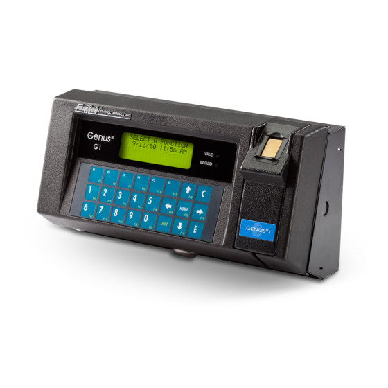
The 3046 WiFi Module provides wireless network connectivity for the CMI Genus™ series
terminals. The WiFi Module functions as an Ethernet to Wireless LAN bridge and connects to
the Genus™ terminal's RJ-45 Ethernet port. The WiFi Module will provide a seamless
connection to an 802.11b compliant Access Point (AP) that is within range. This WiFi Module
is compliant with the IEEE 802.11b standard and provides security and encryption functions
for a secure and reliable network.
This document describes the Genus™ WiFi installation and setup. It also provides
troubleshooting information and a Code 39 barcode table to assist in the setup of the Module
using a digital barcode wand. This provides easy access to special characters that are not
available on the Genus™ terminal keypad, but may be required for SSID, WEP Keys, and
other security parameters.
Please note that the WiFi Module may be referred to as "Module" within this section of the
document.
WiFi Module
Status LEDs
Comm, Link, Power
Power
Port
Revision –
Antenna Cable
Connection
Power
LED
ON/OFF
Switch
RJ45 Connection to
G1 Terminal
Ethernet Cable
(Supplied)
1-23-20
Genus™ G1 Users Manual
Base Mounting
Bracket
Antenna
Base
Mounting Screws
(Supplied)
Antenna
1
Advertisement
Table of Contents

Summary of Contents for Control Module Genus
- Page 1 Code 39 barcode table to assist in the setup of the Module using a digital barcode wand. This provides easy access to special characters that are not available on the Genus™ terminal keypad, but may be required for SSID, WEP Keys, and other security parameters.
- Page 2 Genus™ G1 Users Manual Hardware Installation Antenna and bracket assembly to the G1 Base The antenna assembly is mounted directly to the G1 Base. • Make sure the knockout for the antenna has been removed from the base. • Loosen the top right base screw to fit this bracket.
- Page 3 Genus™ G1 Users Manual Adding the UPS (Option) • The 2050 UPS has a spring tab that must make contact with the ground bar inside the top of the base. • Press the 2050 UPS into the base to the left of the WiFi Module until it snaps securely in place.
- Page 4 Genus™ G1 Users Manual G1 WiFi Connections – Without UPS • Ensure the WiFi Module power switch is off. • Connect Antenna cable to WiFi Module, secure onto the Module. • Connect Ethernet cable from WiFi Module to the G1 Terminal, RJ45 connections.
- Page 5 Genus™ G1 Users Manual G1 WiFi with UPS Connections • Ensure the WiFi Module power switch is off. • Connect Antenna cable to WiFi Module, secure onto the Module • Connect Ethernet cable from WiFi Module to the G1 Terminal, RJ45 connections.
Need help?
Do you have a question about the Genus and is the answer not in the manual?
Questions and answers