
Subscribe to Our Youtube Channel
Related Manuals for Vertiv Liebert SiteLink-2E

Summary of Contents for Vertiv Liebert SiteLink-2E
- Page 1 Liebert® SiteLink-E™ SiteLink-2E, SiteLink-4E, and SiteLink-12E Installation Manual...
- Page 2 Technical Support Site If you encounter any installation or operational issues with your product, check the pertinent section of this manual to see if the issue can be resolved by following outlined procedures. Visit https://www.VertivCo.com/en-us/support/ for additional assistance.
-
Page 3: Table Of Contents
4.4.1 Wiring Port S1 for RS-485 Network—Four-Wire 4.4.2 Wiring Port S1 for RS-485—Two-Wire 4.4.3 Wiring Port S1 for RS-232 4.5 Wiring a Modem for Half-Router Communication—Port S1 5 Specifications Appendices Appendix A: Communication Protocol and Wiring Considerations Vertiv | Liebert® SiteLink-E™ Installation Manual |... - Page 4 Vertiv | Liebert® SiteLink-E™ Installation Manual |...
-
Page 5: Product Overview
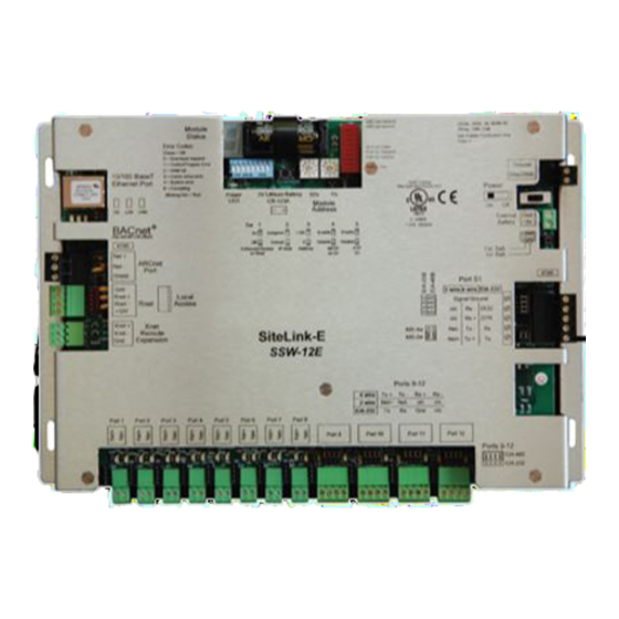
Liebert equipment such as environmental units, UPSs, frequency converters and power distribution units. See Figure 1.1 below for port locations. The Vertiv™ ports, Ports 1 to 12, support IGM, Velocity, ASCII, and Hironet (RS-485). Ports 9 to 12 may be RS-484 or RS-232. Figure 1.1 Liebert SiteLink-E layout—power and communication connections, ports and switches NOTE: This equipment has been tested and found to comply with the limits for a Class A digital device,... - Page 6 This page intentionally left blank. Vertiv | Liebert® SiteLink-E™ Installation Manual |...
-
Page 7: Installing The Liebert Sitelink-E Module
Refer to the following drawings in Enclosure Diagrams below: Enclosure dimensions—overall on the next page Enclosure dimensions—Wall mount on the next page Enclosure dimensions—Floor mount on page 9 2.2 Enclosure Diagrams Figure 2.1 Module dimensions, without enclosure Vertiv | Liebert® SiteLink-E™ Installation Manual |... - Page 8 Figure 2.2 Enclosure dimensions—overall Figure 2.3 Enclosure dimensions—Wall mount Vertiv | Liebert® SiteLink-E™ Installation Manual |...
- Page 9 Figure 2.4 Enclosure dimensions—Floor mount Vertiv | Liebert® SiteLink-E™ Installation Manual |...
- Page 10 This page intentionally left blank. Vertiv | Liebert® SiteLink-E™ Installation Manual |...
-
Page 11: Connect Input Power Wiring
3. Pull the screw terminal connector from the control module’s power terminals labeled 24VAC/DC and Gnd. 4. Connect the transformer wires to the screw terminal connector (see Figure 3.1 on the next page). 5. Apply power to the power supply. Vertiv | Liebert® SiteLink-E™ Installation Manual |... - Page 12 6. Measure the voltage at the Liebert SiteLink-E’s power input terminals to verify that the voltage is within the operating range of 21.6-26.4 VAC. 7. Insert the screw terminal connector into the Liebert SiteLink-E’s power terminals. Figure 3.1 Power connections Vertiv | Liebert® SiteLink-E™ Installation Manual |...
-
Page 13: Communication And Control Wiring
2. If using a four-wire connection, set the jumpers, located behind the terminals, as required for the protocol to be implemented. A guide is at the lower right corner of the module’s housing. Figure 4.1 IGM connections Vertiv | Liebert® SiteLink-E™ Installation Manual |... -
Page 14: Rs-485 And Arc156 Wiring Considerations
DIAG485 that is in the middle of the segment. You can use additional DIAG485s with the bias jumper removed to monitor network communication, but only one DIAG485 may have the bias jumper in place. Vertiv | Liebert® SiteLink-E™ Installation Manual |... -
Page 15: Wiring For Bacnet/Arc156 Network
4. Connect the communication wiring to the control module’s screw terminals labeled Net +, Net - and Shield using the labels near the ARCnet port as a guide. For details, see Figure 4.3 below.. Figure 4.3 BACnet/ARC156 Network port Vertiv | Liebert® SiteLink-E™ Installation Manual |... -
Page 16: Wiring Port S1
(see Figure 4.5 on page 18 for details). 4. Set the RS-232 or RS-485 jumper to RS-485. 5. Set the MS/TP on S1 DIP switch to Enable (On). 6. Set the PTP on S1 DIP switch to Disable (Off). Vertiv | Liebert® SiteLink-E™ Installation Manual |... -
Page 17: Wiring Port S1 For Rs-485-Two-Wire
(see Figure 4.5 on the next page for details). 4. Set the RS-232 or RS-485 jumper to RS-485. 5. Set the MS/TP on S1 DIP switch to Enable (On). 6. Set the PTP on S1 DIP switch to Disable (Off). Vertiv | Liebert® SiteLink-E™ Installation Manual |... -
Page 18: Wiring Port S1 For Rs-232
Liebert recommends using 18-28AWG wiring. • Most RS-232 cables are not twisted pair, but twisted-pair wiring is acceptable. • The distance from the Liebert SiteLink-E to the RS-232 BMS interface should not exceed 50 ft. (15.2m). Vertiv | Liebert® SiteLink-E™ Installation Manual |... -
Page 19: Wiring A Modem For Half-Router Communication-Port S1
3. Set the PTP on S1 DIP switch to Enable (ON). Refer to Figure 4.5 on the previous page for determining the wiring connections. Figure 4.7 Fabricated cable for modem in half-router communication Vertiv | Liebert® SiteLink-E™ Installation Manual |... - Page 20 This page intentionally left blank. Vertiv | Liebert® SiteLink-E™ Installation Manual |...
-
Page 21: Specifications
Real-time clock, battery backup in case of power failure AGENCY Conforms to the Advanced Application Controller (B-AAC) Standard Device Profile, ANSI/ASHRAE Standard 135-2004 BACnet Support (BACnet) Annex L Listings UL-916 (PAZX); cUL-916 (PAZX7); FCC Part 15-Subpart B-Class A Vertiv | Liebert® SiteLink-E™ Installation Manual |... - Page 22 Enhanced Access Rnet 115.2 kbps 3 (.914) Access 1. ARC156 is a unique implementation of the industry standard ARCNET. 2. Port S1 supports only one protocol and one wire type at a time. Vertiv | Liebert® SiteLink-E™ Installation Manual |...
-
Page 23: Appendices
RS-485. Use of the two terms—RS-422 and RS-485—can be confusing in engineering drawings. When drawings include Liebert SiteLink-E wiring details, Liebert suggests labeling any occurrences of RS-422 as “RS-422 (RS-485 four-wire).” Vertiv | Liebert® SiteLink-E™ Installation Manual |... - Page 24 During the transmission of a logic 0 (less than -200mV), the network will be in the space state (ON, logic 0). Liebert’s DIAG boards can serve as bias on RS-485/RS-422 networks. Apply bias in the middle of the network, and apply termination only at the two end devices. Vertiv | Liebert® SiteLink-E™ Installation Manual |...
- Page 26 VertivCo.com | Vertiv Headquarters, 1050 Dearborn Drive, Columbus, OH, 43085, USA © 2017 Vertiv Co. All rights reserved. Vertiv and the Vertiv logo are trademarks or registered trademarks of Vertiv Co. All other names and logos referred to are trade names, trademarks or registered trademarks of their respective owners. While every precaution has been taken to ensure accuracy and completeness herein, Vertiv Co.
Need help?
Do you have a question about the Liebert SiteLink-2E and is the answer not in the manual?
Questions and answers