
Summary of Contents for RFDATATECH SRT150R
- Page 1 SRT PAGING & DATA RECEIVER MANUAL Covering the following: SRT150R, SRT280R, SRT320R, SRT450R & SRT950R Revision B 24/04/03 Page 1 of 18...
-
Page 2: Table Of Contents
CONTENTS INTRODUCTION APPLICATIONS SPECIFICATION RS232 SERIAL PORT PROGRAMMING RSSI SOFTMODEM REMOTE SWITCH APPLICATIONS EXTERNAL AUDIO OUTPUT EXTERNAL DIGITAL OUTPUT 1.10 PAGING MODE 1.11 DATA MODE 1.12 POWER SAVE 1.13 PROGRAMMABLE POWERSAVE 1.14 EXTERNAL POWERSAVE 1.15 STATUS LEDS 1.16 FREQUENCY RANGES SPECIFICATIONS GENERAL RECEIVER... -
Page 3: Introduction
4.4.4 SLEEP MODE 4.4.5 POWER SAVE OPTIONS 4.4.5.1 Save On Time 4.4.5.2 Save Off Time 4.4.5.3 Save Resume Time 4.4.6 SERIAL BAUD RATE, DATA BITS, PARITY & STOP BITS 4.5. PAGING RECEIVER MENU 4.5.1 RADIO DATE RATE 4.5.2 DIGITAL OUTPUT MODE 4.5.3 PAGER TEXT ADDRESS 1 –... -
Page 4: Applications
The SRT Series are high quality receivers with an RS232 output and two addressable digital outputs. Designed for the Paging and Data markets, the products are available in the VHF, 280MHz, 320MHz, UHF & 930MHz bands. SRT series feature f lash processor to allow easy program upgrades or changes should they be required. -
Page 5: Paging Mode
, that The external digital output is direct FSK can be programmed between 150-4800bps. 1.10 PAGING MODE When used as a Paging receiver, the SRT’s internal “softmodem” can be programmed for speeds of 512, 1200 & 2400bps. 1.11 DATA MODE When used as a data receiver, the SRT’s “softmodem”... -
Page 6: Receiver
Connectors: Interface 15way condensed “D” Antenna Approvals: Will Meet current UK, European, USA, Canadian and Australian specifications. RECEIVER: Frequency Range: SRT150R 138 - 175MHz SRT280R 260 – 285MHz SRT320R 320 - 340MHz SRT450R 406 - 512MHz SRT950R 820 – 950MHz... -
Page 7: Serial Interface
Spurious emissions: <2nW Mute response time: <3msec Received Signal Strength (RSSI): Range -120dBm to -40dBm Output voltage 0-5VDC SERIAL INTERFACE Type: RS232 with a programmable serial baud rate of 1200, 2400, 4800 or 9600bps. Data Bits: Programmable 7 or 8. Parity: Programmable Odd, Even, or None. -
Page 8: Programmable Addressing
2.7.1 Programmable Addressing Text address: 4 Addresses & Groups Digital outputs: 1 Address & Group per output 2.7.2 Programmable Text Options Start of text character: None or 1 Start of text ch. mode: Keep, Delete, Insert End of text character: None or 1 End of text ch. -
Page 9: Operation & Interface
OPERATION & INTERFACE CONNECTION DETAILS Control signals are made to the receiver by the 15 way “condensed D” connector. Pin connections are as follows: Ground Ground Ground Ground RX audio Digital output 0 Digital output 1 RSSI voltage +5V supply (note 1) +12V supply (note 1) Note 1: The receiver is supplied either for use with a 5V power supply or for use with a 12V supply, do not connect a 5V supply if the unit has been supplied for use with a 12V supply. -
Page 10: Rx Audio Output
DCD provides an indication that a carrier with valid modulation is being received. RX AUDIO OUTPUT The RX audio output delivers the analogue received audio signal, the signal is muted in the absence of a carrier. RSSI OUTPUT The RSSI output provides an indication of the received signal strength, the DC signal varies in proportion to the logarithmic value of the signal strength over the range 0 –... -
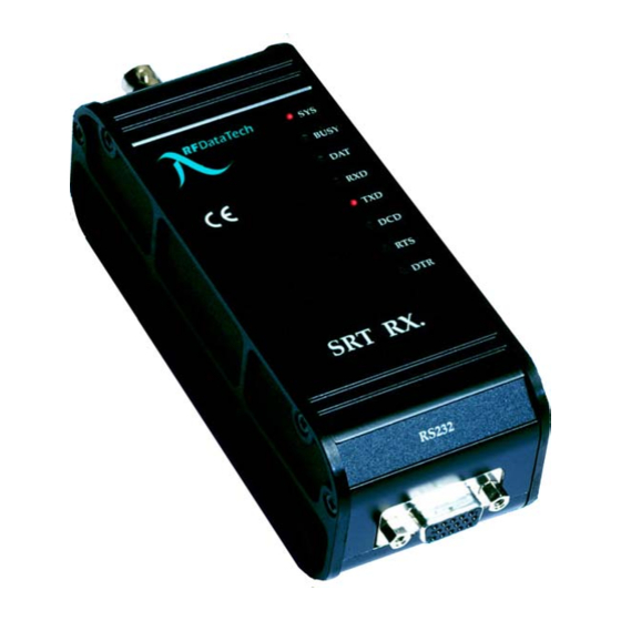
Page 11: Dimensions
DIMENSIONS ANTENNA BUSY R. F. Technologies Ltd. SRT RX. RS232 MOUNTING The SRT is designed for DIN rail mounting to a standard DIN rail or to a short clip bracket. Alternatively, we have a non-clip bracket, that is inserted into the DIN rail slot and the bracket is screwed to the wall/flat plate with the module attached. -
Page 12: Programming
PROGRAMMING SETUP PROGRAMME The DOS set up programme should be copied to a suitable hard drive directory on your PC, the files required are CMP.EXE, DEFAULTS.DAT and RP.CFG. To start the programme open a DOS window and type “CMP”, or alternatively to set the programme up for a different screen or communications port type “CMP/C"... -
Page 13: Edit Notes
the modem but will display a compatibility error message. If this happens a different edition of PC programming software with the same compatibility number may be required. 4.2.3 EDIT NOTES The PC program has a text editor accessed from the main menu that will allow the user to enter the unit’s hard link configuration and add notes if required. -
Page 14: Serial Baud Rate, Data Bits, Parity & Stop Bits
4.4.6 SERIAL BAUD RATE, DATA BITS, PARITY & STOP BITS The format of the serial port signal is set with these options, note that a setting of 7 data bits with no parity will always result in 2 stop bits being output regardless of the setting of the STOP BITS option. -
Page 15: Pocsag Sot Character/Pocsag Sot Mode
4.5.5 POCSAG SOT CHARACTER/POCSAG SOT MODE This field allows various operations on a start of text character, the SOT MODE field only appears if a SOT character has been entered. The SOT character must be entered as a hex value. If the SOT mode is set to keep or delete no text is output until the first occurrence of the SOT character, if the mode is keep the SOT character and the following text are output, if the mode is delete only the following text is output. - Page 16 1 0 0 0 0 1 1 ON FOR 30ms 1 0 0 0 1 0 0 ON FOR 40ms 1 0 0 0 1 0 1 ON FOR 50ms 1 0 0 0 1 1 0 ON FOR 60ms 1 0 0 0 1 1 1 ON FOR 70ms 1 0 0 1 0 0 0...
-
Page 17: Data Receiver Menu
DATA RECEIVER MENU 4.6.1 RADIO BAUD RATE Sets the baud rate of the internal radio modem, (currently 150 – 4800 baud within the prescribed 12.5KHz channel) this setting does not govern the speed at which the serial port operates which should be set either at the same speed or a higher speed. The radio baud rate should be set at the minimum possible to maintain the required throughput, lower speeds will give better results in poor signal conditions. -
Page 18: Externnal Audio Receiver Menu
EXTERNAL AUDIO RECEIVER MENU 4.7.1 CARRIER MUTE This function allows the carrier mute to be enabled or disabled EXTERNAL DIGITAL RECEIVER MENU 4.8.1 RADIO BAUD RATE The Data baud rate can be set between 150 – 4800bps 4.8.2 RX SIGNAL POLARITY This enables the selection of a true or inverted signal Revision B 24/04/03 Page 18 of 18...
Need help?
Do you have a question about the SRT150R and is the answer not in the manual?
Questions and answers