Advertisement
Quick Links
sauder.com
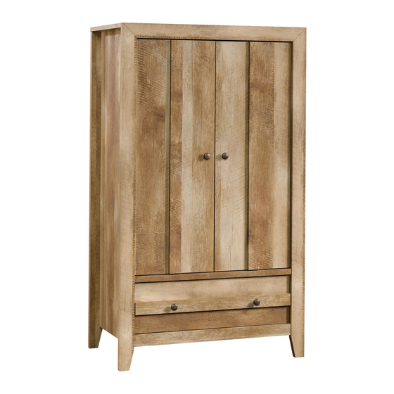
Armoire
Dakota Pass Collection | 419077
Need help? Visit Sauder.com to view video assembly tips or chat with a live rep.
Prefer the phone? Call 1-800-523-3987.
Share your journey!
You could use a new
hide-and-seek spot.
NOTE: THIS INSTRUCTION
BOOKLET CONTAINS IMPORTANT
SAFETY INFORMATION.
PLEASE READ AND KEEP FOR
FUTURE REFERENCE.
English pg 1-28
Français pg 29-32
Español pg 33-36
Lot # 376556
09/28/15
Purchased: __________________
Be sure to give us a ring before
making any returns. 1-800-523-3987
Advertisement

Subscribe to Our Youtube Channel
Related Manuals for Sauder Dakota Pass Armoire 419077


Summary of Contents for Sauder Dakota Pass Armoire 419077
- Page 1 Dakota Pass Collection | 419077 NOTE: THIS INSTRUCTION BOOKLET CONTAINS IMPORTANT SAFETY INFORMATION. Need help? Visit Sauder.com to view video assembly tips or chat with a live rep. PLEASE READ AND KEEP FOR FUTURE REFERENCE. Prefer the phone? Call 1-800-523-3987.
- Page 2 DRAWER FRONT MOLDING (1) DOOR (2) RIGHT DRAWER SIDE (1) ADJUSTABLE SHELF (1) LEFT DRAWER SIDE (1) RIGHT FRONT LEG (1) DRAWER BACK (1) LEFT FRONT LEG (1) D985 DRAWER BOTTOM (1) BACK LEG (2) DRAWER BRACE (1) Page 2 419077 www.sauder.com/services...
- Page 3 Part Identifi cation D985 www.sauder.com/services 419077 Page 3...
- Page 4 This is a permanent label. Do not attempt to remove! 04/10 332296 (Refer to step 22 for proper location and application) SAFETY DRYWALL NAIL - 46 RUBBER SLEEVE - 4 METAL PIN - 4 ANCHOR - 1 Page 4 419077 www.sauder.com/services...
- Page 5 BLACK 1/2" FLAT HEAD SCREW - 8 BLACK 2-1/4" FLAT HEAD SCREW - 8 30S BLACK 1-9/16" FLAT HEAD SCREW - 5 GOLD 1" MACHINE SCREW - 2 BLACK 1" PAN HEAD SCREW - 9 SILVER 1-1/2" MACHINE SCREW - 2 www.sauder.com/services 419077 Page 5...
- Page 6 Assemble your unit on a carpeted fl oor or on the empty å carton to avoid scratching your unit or the fl oor. To begin assembly, push twelve SAUDER TWIST-LOCK® å FASTENERS (10F) into the large holes in the ENDS (A and B), BOTTOM (D), and SHELF (E).
- Page 7 Push twelve HIDDEN CAMS (1F) into the ENDS (A å and B), TOP (C), and DRAWER BRACE (M67). Arrow Arrow (12 used) Arrow Hole The arrow in the HIDDEN CAM must point toward the hole in the edge of the board. www.sauder.com/services 419077 Page 7...
- Page 8 J), DRAWER FRONT (L), and TOP MOLDING (M). Just think. The sooner you do this, the sooner Tap two MOLDING CONNECTORS (17F) into the notches å you do something else. in the TOP MOLDING (M). Flat end (12 used) Flat end Page 8 419077 www.sauder.com/services...
- Page 9 Use a BLACK 9/16" LARGE HEAD SCREW (1S). NOTE: Be sure to position the BRACKET exactly as shown å in the enlarged diagram. BLACK 9/16" LARGE HEAD SCREW Short fl at edge (1 used in this step) www.sauder.com/services 419077 Page 9...
- Page 10 BLACK 2-1/4" FLAT HEAD SCREW (8 used in this step) (2 used) These surfaces should be even. Edge with HIDDEN CAMS These surfaces should be even. Angled edge Edge with HIDDEN CAMS These surfaces should be even. Page 10 419077 www.sauder.com/services...
- Page 11 Caution TWIST-LOCK® FASTENERS. Do not stand the unit upright without the BACK fastened. The unit may collapse. How to use the SAUDER TWIST-LOCK ® FASTENER 1. Insert the dowel end of the FASTENER into the hole of the adjoining part.
- Page 12 - L O F A S T E N ® E R S S u r f a c i t h I S T - L O F A S T E N ® E R S Page 12 419077 www.sauder.com/services...
- Page 13 Slide the BOTTOM MOLDING* (O) onto the notched edge å of the BOTTOM (D). *U.S. Patent No. 5,499,886 å Notched edge Slide the SHELF MOLDING (N) onto the notched edge. Slide the BOTTOM MOLDING (O) onto the notched edge. www.sauder.com/services 419077 Page 13...
- Page 14 Rome. This can be built in a day. Edge with HIDDEN CAMS i t h o K ® f a c L O C S u r I S T - E R S T E N F A S Page 14 419077 www.sauder.com/services...
- Page 15 MOLDING (M) insert into the notches in the FRONT LEGS. You may need to gently tap them in with your hammer. NOTE: Be sure the WOOD DOWELS in the FRONT LEGS å insert into the holes in the ENDS. Angled edge www.sauder.com/services 419077 Page 15...
- Page 16 ENDS (A and B). Use four GOLD 5/16" FLAT HEAD SCREWS (3S) through holes #1 and #3. *patent pending glide system å Glide end Glide end Glide end GOLD 5/16" FLAT HEAD SCREW (4 used in this step) Page 16 419077 www.sauder.com/services...
- Page 17 (46 used in this step) NOTE: Perforations have been provided for access å through the BACK. Carefully cut out the holes needed. This large hole must be here. These holes must line up over the SHELF (E). www.sauder.com/services 419077 Page 17...
- Page 18 Step 13 Fasten the DOOR MOLDINGS (P) to the DOORS (G). Use å six BLACK 1" PAN HEAD SCREWS (60S). BLACK 1" PAN HEAD SCREW (6 used in this step) Page 18 419077 www.sauder.com/services...
- Page 19 Step 14 Fasten two HINGES (14H) to each DOOR (G). Use eight å BLACK 1/2" FLAT HEAD SCREWS (11S). BLACK 1/2” FLAT HEAD SCREW (8 used in this step) www.sauder.com/services 419077 Page 19...
- Page 20 Fasten a KNOB (28K) to the DOOR (G). Use a GOLD 1" å MACHINE SCREW (50S). Repeat this step for the other DOOR (G). å Hinge See the next step for DOOR adjustments. å GOLD 1" MACHINE SCREW (2 used in this step) Page 20 419077 www.sauder.com/services...
- Page 21 To adjust the DOORS in or out (depth), loosen the mounting å screw one turn and move the DOORS in or out, as needed. Tighten the mounting screw after making adjustments. Mounting screw (depth) Adjusting screw (horizontal) (vertical adjustment) www.sauder.com/services 419077 Page 21...
- Page 22 Fasten the DRAWER BACK (D80) to the DRAWER Fasten the DRAWER BRACE (M67) to the DRAWER å å SIDES (D30 and D31) and DRAWER BRACE (M67). Use FRONT (L). Tighten one HIDDEN CAM. five BLACK 1-9/16" FLAT HEAD SCREWS (30S). Page 22 419077 www.sauder.com/services...
- Page 23 å Glide end Screw head - turn CAM to line up holes in the SLIDES with holes in DRAWER SIDES Glide end (4 screws per drawer) GOLD 5/16" FLAT HEAD SCREW (4 used in this step) www.sauder.com/services 419077 Page 23...
- Page 24 DRAWER FRONT MOLDING, and into the KNOBS. BLACK 1" PAN HEAD SCREW (3 used for the DRAWER FRONT MOLDING) F i n i s h e u r f a SILVER 1-1/2" MACHINE SCREW (2 used for the KNOBS) Page 24 419077 www.sauder.com/services...
- Page 25 NOTE: Before moving your unit to a diff erent location, unscrew the SAFETY DRYWALL ANCHOR (61M) from your wall. å The nylon sheath will remain behind your wall. BLACK 9/16" LARGE HEAD SCREW (1 used in this step) www.sauder.com/services 419077 Page 25...
- Page 26 PINS (1R). Insert the METAL PINS into the hole locations of Almost time to your choice in the ENDS (A and B). Set the ADJUSTABLE celebrate! With a nap. SHELF (H) onto the METAL PINS. (4 used) Page 26 419077 www.sauder.com/services...
- Page 27 Once applied, do not try to remove it. Use of tip-over restraints may only reduce, but not eliminate, the risk of tip-over. 25 lbs. 30 lbs. 35 lbs. 15 lbs. www.sauder.com/services 419077 Page 27...
- Page 28 #2. The higher the screw in the oblong hole, the higher your drawer front will be. The lower the screw, the lower the drawer front. Page 28 419077 www.sauder.com/services...
- Page 29 EXTRÉMITÉ DROITE ..........1 EXCENTRIQUE ESCAMOTABLE ....12 pour future référence. EXTRÉMITÉ GAUCHE ..........1 VIS D'EXCENTRIQUE ..........12 Pour contacter Sauder DESSUS ................1 10F FIXATION TWIST-LOCK® ........12 en ce qui concerne cet DESSOUS ................1 15F CHEVILLE EN BOIS ...........2 élément, faire référence...
- Page 30 Fixer l'EXTRÉMITÉ GAUCHE (B) au DESSUS (C). Serrer deux FIXATIONS TWIST-LOCK®. Pour commencer l'assemblage, enfoncer douze FIXATIONS TWIST-LOCK® SAUDER (10F) dans les gros trous dans les Utilisation de la FIXATION TWIST-LOCK® SAUDER EXTRÉMITÉS (A et B), le DESSOUS (D) et la TABLETTE (E).
- Page 31 VIS avant de les serrer toutes à bloc. Fixer un BOUTON (28K) à la PORTE (G). Utiliser une VIS À MÉTAUX 25 mm DORÉE (50S). Répéter cette étape pour l'autre PORTE (G). Voir l'étape suivante pour réglages des PORTES. www.sauder.com/services 419077 Page 31...
- Page 32 Ceci complète l'assemblage. Nettoyer à l’ a ide d’une encaustique REMARQUE : Avant de déplacer l’unité vers un emplacement pour meubles ou d’un chiff on humide. Essuyer. diff érent, dévisser le DISPOSITIF DE SÉCURITÉ POUR PLACOPLÂTRE (61M) du mur. La gaine en nylon Page 32 419077 www.sauder.com/services...
- Page 33 EXTREMO IZQUIERDO ..........1 58G MANGUITO DE GOMA GRANDE ....1 pour future référence. PANEL SUPERIOR ............1 14H BISAGRA ................4 Pour contacter Sauder FONDO .................1 28K POMO ..................4 en ce qui concerne cet ESTANTE ................1 ETIQUETA DE ADVERTENCIA ......1 élément, faire référence...
- Page 34 Fije el EXTREMO IZQUIERDO (B) al PANEL SUPERIOR (C). Apriete dos SUJETADORES TWIST-LOCK®. Para comenzar el ensamblaje, empuje doce SUJETADORES TWIST-LOCK® SAUDER (10F) dentro de los agujeros grandes de Cómo utilizar el SUJETADOR TWIST-LOCK® SAUDER los EXTREMOS (A y B), del FONDO (D) y del ESTANTE (E).
- Page 35 NOTA: La cabeza de tornillo del EXCÉNTRICO debe ser visible a DORADO PARA METAL de 25 mm (50S). través del agujero alargado de la CORREDERA. Repita este paso para la otra PUERTA (G). Consulte el próximo paso para ajustar la PUERTA. www.sauder.com/services 419077 Page 35...
- Page 36 Seque con un paño. NOTA: Antes de trasladar la unidad a otra ubicación, desatornille el ANCLAJE DE SEGURIDAD PARA EL DRYWALL (61M) de su pared. La cubierta de nailon permanecerá detrás de su pared. Page 36 419077 www.sauder.com/services...
- Page 37 • Ne pas pousser le mobilier, surtout sur la être très lourd. moquette. Se faire aider par une autre personne pour soulever l’élément et le mettre en place. • Cette unité doit être placée contre un mur. www.sauder.com/services 419077 Page 37...
- Page 38 • No empuje la unidad, especialmente sobre ser muy pesado. un piso alfombrado. Pide la ayuda de otra persona para levantar la unidad y colocarla en lugar. • Esta unidad debe ser colocada contra una pared. Page 38 419077 www.sauder.com/services...
- Page 39 GARANTIE LIMITÉE DE 5 ANS 1. Sauder Woodworking Co. (Sauder®) off re une couverture de garantie limitée à l’ a cheteur 4. La présente garantie ne s’ a pplique qu’ a ux défauts garantis qui se produisent pour initial du présent produit pendant une période de cinq ans à...
- Page 40 Dear Valued Customer: So, how did it go? Thanks so much for choosing Sauder® furniture. I hope the Set a world record for speed? purchase and assembly process was a positive experience Feeling good about yourself? and you feel good about the furniture you just built. If you Nice.
Need help?
Do you have a question about the Dakota Pass Armoire 419077 and is the answer not in the manual?
Questions and answers