Advertisement
KNOW YOUR PRODUCT
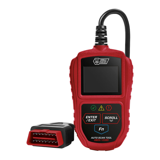
AUTOMOTIVE
DIAGNOSTIC
SCANNER
• OBD2 CODE READER
• SUITS MOST VEHICLES
FROM 1996 ONWARDS
• READ & CLEAR
DIAGNOSTIC TROUBLE
CODES
INSTRUCTION MANUAL
WARNING: Read all safety warnings and all instructions. Failure to follow
the warnings and instructions may result in electric shock, fire and/or serious
injury. Save all warnings and instructions for future reference.
0721
Advertisement
Table of Contents

Summary of Contents for Full Boar FBAST-100
- Page 1 KNOW YOUR PRODUCT AUTOMOTIVE DIAGNOSTIC SCANNER • OBD2 CODE READER • SUITS MOST VEHICLES FROM 1996 ONWARDS • READ & CLEAR DIAGNOSTIC TROUBLE CODES INSTRUCTION MANUAL WARNING: Read all safety warnings and all instructions. Failure to follow the warnings and instructions may result in electric shock, fire and/or serious injury.
-
Page 2: Specifications
SPECIFICATIONS - MODEL NO. FBAST-100 Support: OBD2 Compliant vehicles Input: 8 to 18V Display: 2.0" TFT Colour screen (220 x 176 dpi) Operating temp.: 0°C to 50°C Storage temp.: -20°C to 70°C Weight: 0.21 kg KNOW YOUR PRODUCT CHECK OBD/EOBD... - Page 3 KNOW YOUR PRODUCT (cont.) 1. TFT Colour screen Indicates setup, scan, menu options and test results. 2. Red LED Indicates there is a problem in one or more of the vehicle’s systems. The red LED is also used to show that DTCs are present. DTCs are shown on the Scan Tool’s screen.
-
Page 4: Table Of Contents
TABLE OF CONTENTS SPECIFICATIONS............Page 02 KNOW YOUR PRODUCT...........Page 02 INTRODUCTION............Page 05 SAFETY INSTRUCTIONS...........Page 06 GENERAL INFORMATION........Page 07 MENU................Page 10 OPERATION..............Page 12 TROUBLESHOOTING..........Page 25 MAINTENANCE............Page 26 DESCRIPTION OF SYMBOLS........Page 27 CONTENTS...............Page 27 WARRANTY...............Page 28... -
Page 5: Introduction
INTRODUCTION Congratulations on purchasing a Full Boar Automotive Diagnostic Scanner. The Full Boar Automotive Diagnostic Scanner FBAST-100 is designed for troubleshooting most cars and light trucks from 1996 onwards. Use this Automotive Diagnostic Scanner to diagnose and erase faults relating to spark plugs, valves and many more, whilst the live data feature allows for more precise diagnosis of faults. -
Page 6: Safety Instructions
SAFETY INSTRUCTIONS WARNING! Save all warnings and instructions for future reference. WARNING! Read all safety warnings and all instructions. Failure to follow the warnings and instructions may result in electric shock, fire and/or serious injury. - This appliance is not intended for use by young or infirm persons unless supervised by a responsible person to ensure that they can use the appliance safely. -
Page 7: General Information
GENERAL INFORMATION OBD2 Readiness monitors An important part of a vehicle’s OBD2 system is the Readiness Monitors, which are indicators used to find out if all of the emissions components have been evaluated by the OBD2 system. They are running periodic tests on specific systems and components to ensure that they are performing within allowable limits. - Page 8 GENERAL INFORMATION (cont.) OBD2 Monitor readiness status OBD2 systems must indicate whether or not the vehicle’s PCM’s monitor system has completed testing on each component. Components that have been tested will be reported as “Ready”, or “Complete”, meaning they have been tested by the OBD2 system.
- Page 9 GENERAL INFORMATION (cont.) OBD2 Definitions • Power-train control module (PCM) – OBD2 terminology for the on-board computer that controls engine and drive train. • Malfunction indicator light (MIL) – Malfunction Indicator Light (Service Engine Soon, Check Engine) is a term used for the light on the instrument panel. It is to alert the driver and/or the repair technician that there is a problem with one or more of vehicle’s systems and may cause emissions to exceed federal standards.
-
Page 10: Menu
MENU KNOW YOUR PRODUCT WARNING! Read and understand the warnings before setup. The Automotive Diagnostic Scanner is used to check engine of most OBD2 compliant vehicles from 1996 onwards with standard sized 16-Pin Data Link Connector (DLC). Your DLC is usually located near centre under the instrument panel (dash), under or around the driver’s side of most vehicles (fig. - Page 11 MENU (cont.) Diagnostic trouble codes (DTC) OBD2 Diagnostic Trouble Codes are codes that are stored by the on-board computer diagnostic system in response to a problem found in the vehicle. These codes identify a particular problem area and are intended to provide you with a guide as to where a fault might be occurring within a vehicle.
-
Page 12: Operation
OPERATION Setup menu WARNING! Do not connect or disconnect scan tool with ignition on or engine running. 1. Connect OBD2 16-pin connector (6) into the DLC. 2. Turn the ignition on. Setup can be done with engine off or engine running. When the scan tool is powered on, it displays a CHECK home screen (fig. - Page 13 Key Beep Set Tool Setup Status Beep Set Language Language Fn key set Nederlands Unit of measure Previous Menu OPERATION (cont.) English Key Beep Set Francais Status Beep Set Espanol Fn key set Language • Unit of measure: The default units from the factory is Metric, English (imperial) Deutsch Previous Menu can me manually selected.
- Page 14 Status Beep Set OPERATION (cont.) • Fn key set: For setting the Quick-test function button (8) including I/M readiness status, trouble code, default live data and all datastream. 1. From the Tool Setup screen (fig. 4), use the Scroll button (7) to select Fn Key Set and Fn Key Set press the Enter/Exit button (5).
- Page 15 OPERATION (cont.) About menu This function allows viewing of some important information such as serial number and software version number of the scanner. 1. From the home screen (fig. 10), use the Scroll button (7) to select the About interface , and press Enter/Exit button (5). CHECK OBD/EOBD Ready Test...
- Page 16 OPERATION (cont.) Diagnostic menu - OBD2 test When more than one vehicle control module is detected by the scan tool, you will be prompted to select the module where the data may be retrieved. The most often to be selected are the Power train Control Module [PCM] and Transmission Control Module [TCM].
- Page 17 CHECK CHECK OBD/EOBD Ready Test OBD/EOBD Ready Test OPERATION (cont.) Setup About Setup About 5. View a summary of the system status (MIL status, DTC counts, Monitor status) on the Monitor Status Monitor Status TFT colour screen (1) (fig. 13). MIL status MIL status CHECK...
- Page 18 Erase Codes View Freeze Frame I/M Readiness Vehicle Information OPERATION (cont.) 2. Use the Scroll button (7) to select Stored Read Codes Codes or Pending Codes and press Enter/ Exit button (5) to confirm (fig. 16). Diagnostic Menu Stored Codes If there is not any Diagnostic Trouble Code Read Codes Pending Codes...
- Page 19 OPERATION (cont.) Diagnostic menu - Erase codes: This module can be used to clear DTCs in the Diagnostic Menu system. Erasing the Diagnostic Trouble Codes may allow the automotive scan Read Codes tool to delete not only the codes from the vehicle’s on-board computer, but also CHECK “Freeze Frame”...
- Page 20 OPERATION (cont.) Diagnostic menu - Date stream: Allows viewing of live or real time PID data of vehicle’s computer module(s). For the vehicles with more ECUs, more live datas will be found and showed. The max live datas arrive at 300 for some cars. However, the live data real quantity depend on each car ECU.
- Page 21 Erase Codes View Freeze Frame I/M Readiness OPERATION (cont.) Vehicle Information Note: The number to the right of the TFT Freeze Frame colour screen (1) indicates sequence of highlighted item (fig. 24). DTCFRZF P1633 3. If retrieved information covers more than FUELSYS2 one screen, use the Scroll button (7), as LOAD_PCT (%)
- Page 22 Erase Codes View Freeze Frame I/M Readiness Vehicle Information OPERATION (cont.) Diagnostic Menu An I/M Readiness Status result of “NO” does not necessarily indicate that the Read Codes vehicle being tested will fail the state I/M inspection. For some states, one or I/M Readiness more such monitors may be allowed to be “Not Ready”...
- Page 23 OPERATION (cont.) Diagnostic menu - Vehicle info: This function enables retrieval of Vehicle Identification Diagnostic Menu Diagnostic Menu No. (VIN), Calibration ID Nos. (CINs), Read Codes Diagnostic Menu Diagnostic Menu Read Codes Calibration Verification Nos. (CVNs) and In-use Erase Codes Read Codes Read Codes Performance Tracking on 2000 and newer...
- Page 24 OPERATION (cont.) Diagnostic menu - Exit the OBD2 test: 1. Use the Scroll button (7) to select Previous Menu from the Diagnostic Manu and press Enter/Exit button (5) to confirm. 2. An advisory warning message asking your confirmation, press Enter/Exit button (5) to confirm your exit.
-
Page 25: Troubleshooting
TROUBLESHOOTING Communication error When vehicle ignition is off or engine not running the automotive diagnostic scanner cannot communicate with the engine system, this message will be displayed. You will need to do the following to check: 1. Verify that the ignition is ON or the engine is running. 2. -
Page 26: Maintenance
TROUBLESHOOTING (cont.) Cannot use the diagnostic function When you select the Diagnostic OBD/EOBD interface in the home screen, it only shows the I/M Readiness status, the scan tool may be in Ready test mode. You will need to do the following: 1. -
Page 27: Description Of Symbols
DESCRIPTION OF SYMBOLS Volts Amperes Regulatory Compliance Mark Warning (RCM) Read Instruction Manual CARING FOR THE ENVIRONMENT Power tools that are no longer usable should not be disposed of with household waste but in an environmentally friendly way. Please recycle where facilities exist. Check with your local council authority for recycling advice. -
Page 28: Warranty
WARRANTY YOUR WARRANTY FORM SHOULD BE RETAINED BY YOU AT ALL TIMES. IN ORDER TO MAKE A CLAIM UNDER THIS WARRANTY YOU MUST RETURN THE PRODUCT TO YOUR NEAREST BUNNINGS WAREHOUSE (see www.bunnings.com.au or www.bunnings.co.nz for store locations) WITH YOUR BUNNINGS REGISTER RECEIPT. PRIOR TO RETURNING YOUR PRODUCT FOR WARRANTY PLEASE TELEPHONE OUR CUSTOMER SERVICE HELPLINE: Australia 1800 951 371 New Zealand 0800 647 840...
Need help?
Do you have a question about the FBAST-100 and is the answer not in the manual?
Questions and answers