Advertisement
Quick Links
Quick Installation Guide
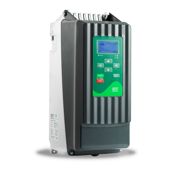
NFO Sinus Optimal
1
Mechanical installation
When unpacking the inverter, carefully inspect the product and make sure it has not been damaged during
transportation. An inverter with cracks, dents or other visual damage shall not be installed.
The inverter must not be installed so that outlet air from another inverter or other equipment blows directly
into the inverter air intake. A minimum of 80 mm clearance must be kept above and below the inverter.
All terminals are accessed by opening the plastic cover. To be able to use the snap-and-hold-open
functionality of the cover, a free space of 200 mm is required above the inverter.
During installation it is important that no foreign objects, such as cable strands or screws, fall into the
inverter as a short circuit may occur. Drilling in chassis or cover is not allowed.
After installation, make sure all grommets at the cable entries are mounted and that the cover is closed and
secured with its screws to avoid access to dangerous voltages.
1.1 Mounting
Unscrew the two lower captive screws and loosen the inverter from the backplate.
Fasten backplate to a vertical surface using four screws. Make sure that the top mounting screws are
sufficiently strong to hold the entire weight of the inverter.
Place the inverter on the backplate by mating the chassis cut-out to the backplate hooks. Tighten the lower
captive screws on both sides.
NFO Drives AB 2021
1
3006468-2022-04
201016‐2 Quick Installation Guide
Advertisement

Related Manuals for Exhausto NFO Sinus Optimal

Summary of Contents for Exhausto NFO Sinus Optimal
- Page 1 3006468-2022-04 Quick Installation Guide NFO Sinus Optimal Mechanical installation When unpacking the inverter, carefully inspect the product and make sure it has not been damaged during transportation. An inverter with cracks, dents or other visual damage shall not be installed.
- Page 2 3006468-2022-04 Electrical installation Connect mains power to terminals L1, L2, L3 and PE. Connect motor cable to terminals U, V, W and PE using standard unshielded cable. Never install contactors or switches between the inverter (terminals U, V and W) and the motor that intentionally or unintentionally may be used to disconnect the motor from inverter output.
- Page 3 3006468-2022-04 Initial setup and tuning 3.1 Select application First time powered up after installation, or after performing a factory reset of parameters, the installer will be prompted to select application type for the inverter. The purpose of selecting application is to preset acceleration and deceleration ramps to a value suitable for the application in question.
- Page 4 3006468-2022-04 Keyboard and menu summary Button Function Enter into parameter or parameter-group. Save parameter. Enter/toggle between normal screen and setup menu tree. Leave parameter, parameter-group or leave parameter unsaved. Toggle Operating mode between Manual and Auto. Starts motor in Auto mode if Run signal active. Starts motor in Manual mode.
Need help?
Do you have a question about the NFO Sinus Optimal and is the answer not in the manual?
Questions and answers