Advertisement
KNX Metering gateway
KNX Metering gateway
Art. No. : 135 16 140
Operating instructions
1 Safety instructions
Electrical devices may only be mounted and connected by electrically skilled
persons.
Serious injuries, fire or property damage possible. Please read and follow manual fully.
Danger of electric shock. During installation and cable routing, comply with the
regulations and standards which apply for SELV circuits.
Fire hazard. Only use limited-capacity power sources according to EN 60950-1. Observe
the technical data.
These instructions are an integral part of the product, and must remain with the end
customer.
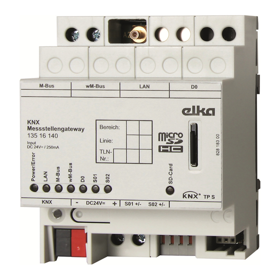
2 Device components
(1) Connection for M-bus devices
(2) Connection for wM-bus antenna
(3) Ethernet connection
(4) D0 connection for optical communication head
(5) Slot for micro SD card
(6) For future expansions; has no function
(7) Two S0 connections
(8) Power supply connection
(9) KNX connection
(10) Status LEDs
82594604
Figure 1
1/9
05.02.2016
Advertisement
Table of Contents

Summary of Contents for Elka 135 16 140
- Page 1 KNX Metering gateway KNX Metering gateway Art. No. : 135 16 140 Operating instructions 1 Safety instructions Electrical devices may only be mounted and connected by electrically skilled persons. Serious injuries, fire or property damage possible. Please read and follow manual fully.
- Page 2 KNX Metering gateway 3 Function System information This device is a product of the KNX system and complies with the KNX directives. Detailed technical knowledge obtained in KNX training courses is a prerequisite to proper understanding. The function of this device depends upon the software. Detailed information on loadable software and attainable functionality as well as the software itself can be obtained from the manufacturer´s product database.
-
Page 3: Operation
KNX Metering gateway 4 Operation LED function The LEDs indicate the device and communication statuses. Depending on the direction of communication, the LED signals may overlap or only be displayed briefly. Power/Error: Red: Internal error Red flashing: Error during KNX commissioning Yellow: External commissioning (meter scan) active Yellow flashing: Commissioning;... -
Page 4: Fitting And Electrical Connection
KNX Metering gateway 5.1 Fitting and electrical connection Fitting the device Observe the temperature range. Ensure adequate cooling. Mount device on DIN rail. Connecting the device i When selecting the measurement points to be connected and when laying cable, make sure all dangerous voltages have been disconnected. - Page 5 KNX Metering gateway Figure 4 Connect PC or router Saved data can be read out via the integrated Ethernet interface (3). A PC or a mobile device can be connected either directly, via a network distributor or via a router. Figure 5: Connection example for PC or router Use network cables with RJ45 connectors.
- Page 6 KNX Metering gateway Figure 6 Use, e.g., J-Y(St)Y 2x2x0.8 as bus cable. Connect measurement points to M-bus connection at terminal M-Bus (1). Connect antenna for measurement points with wireless M-bus interface Figure 7 Place the antenna outside of the distribution board and insert antenna cable into the distribution board.
- Page 7 KNX Metering gateway Figure 8 Use, e.g., J-Y(St)Y 2x2x0.8 as bus cable. Connect a measurement point to each connection, S0 1 or S0 2. Connect measurement point with D0 interface Figure 9 Use RJ10 connector to connect D0 measurement head to socket (4). Set optical communication head on the measurement point optical interface.
-
Page 8: Technical Data
6 Appendix Simplified Declaration of Conformity Hereby Elka Elektronik GmbH declares that the radio system type KNX measurement point gateway, art. no. 13516140 corresponds to the directive 2014/53/EU. The complete text of the EU Declaration of Conformity is available under the Internet address: www.elka.de/compliance... -
Page 9: Warranty
Our products are under warranty within the scope of the statutory provisions. Please return the device, postage paid, to our central service department, giving a brief description of the fault: ELKA-Elektronik GmbH ServiceCenter Hohe Steinert 10 58509 Lüdenscheid Germany Tel.: +49 2351 176-4440...
Need help?
Do you have a question about the 135 16 140 and is the answer not in the manual?
Questions and answers