Table of Contents
Advertisement
Quick Links
Advertisement
Table of Contents

Summary of Contents for Tolomatic STAC6
- Page 1 STAC6 Drives and Microstepping Motors User Manual STAC6 DRIVES AND MICROSTEPPING MOTORS are DISCONTINUED. Replacements are not available. For legacy STAC6 drives and Microstepping Motors use this manual for reference only. 3600-4645_02_AMPSTE LINEAR SOLUTIONS MADE EASY LINEAR SOLUTIONS MADE EASY...
- Page 2 © 2022 Tolomatic Tolomatic, Incorporated. All rights reserved. Tolomatic and Excellence In Motion are registered trademarks of Tolomatic Incorporated. All other products or brand names are trademarks of their respective holders. 202204130849...
-
Page 3: Table Of Contents
Size 23 Motors ....................2.1 Size 34 Motors ....................2.2 Rec. Motor Dimensions ................2.4 - 2.5 Chapter 3: Configuration STAC6 Configurator Software ..............3.1 - 3.3 Configuring the Motor ................3.4 - 3.7 Input and Outputs .................. 3.8 - 3.10 Status Monitor ....................3.11 Chapter 4: Standard Accessories &... -
Page 4: List Of Figures
Block Diagram ............[STAC6-S] [STAC6-Si] and SI Drive Mounting Dimensions ...........i [STAC6-S] [STAC6-Si] STAC6 Applied Motion Products (Motor Control) ............1.3 STAC6 Error Codes ....................1.5 422 Wiring ........................1.9 485 Wiring ......................1.10 AC Connection ......................1.11 Motor Cable Wiring ....................1.12 HD 15 Pinouts......................1.13 Encoder Dialog ......................1.14... - Page 5 Connecting an PNP Type Prox. Sensor ..............4.10 Output Circuit Schematic Diagram ................4.11 Sinking Output ......................4.11 4.10 Sourcing Output ......................4.11 4.11 Driving a Relay ......................4.12 4.12 Mechanical Outline ....................4.12 4.13 Pin Assignments .....................4.13 STAC6 Drives and Microstepping Motors: User Manual (Discontinued Product) • iii •...
-
Page 6: Overview
DC Bus Voltage Nominal 330 VDC (at 240 VAC line input) AC Input Voltage 94—265VAC, 50/60Hz Protection Over-Voltage, Under voltage, Over-Temp, External Output Shorts (Phase to-Phase, Phase-to-Ground), Inter Amplifier Shorts STAC6 Drives and Microstepping Motors: User Manual (Discontinued Product) • iv •... - Page 7 0.25 to 1.5 rps Auto Setup Measures motor parameters and configures tuning and observer parameters Self Test Identifies the presence of an encoder and determines resolution. Diagnoses miswires and open phases STAC6 Drives and Microstepping Motors: User Manual (Discontinued Product) • v •...
- Page 8 Interface RS-232 and RS-485 Bus Encoder Differential line receivers suitable for 200 KHz or greater Ambient Temperature 0 to 55°C (32 - 158°F) Humidity 90% non-condensing STAC6 Drives and Microstepping Motors: User Manual (Discontinued Product) • vi •...
-
Page 9: Control Options
• Graphical point and click format combines motion, I/O, and operator interface functionality for simple machine sequencing. • Easily integrates with other devices on the machine (Sensors, PLCs etc). STAC6 Drives and Microstepping Motors: User Manual (Discontinued Product) • vii •... - Page 10 O V E R V I E W Figure 1: DS[STAC6-S], SI[STAC6-Si] Block Diagram STAC6 Drives and Microstepping Motors: User Manual (Discontinued Product) • viii •...
- Page 11 O V E R V I E W Figure 2: DS[STAC6-S], SI[STAC6-Si] Drive Mounting Dimensions STAC6 Drives and Microstepping Motors: User Manual (Discontinued Product) • ix •...
-
Page 12: Chapter 1: Hardware
It is vital to ensure that all system components are connected to earth ground. Electrical safety is impossible without a low-resistance earth connection. The STAC6 contains electrostatically sensitive components that can STAC6 Drives and Microstepping Motors: (Discontinued Product) User Manual... - Page 13 Failure to observe these precautions could result in serious bodily injury, damage to the equipment,or operational difficulty. STAC6 Drives and Microstepping Motors: User Manual (Discontinued Product) • 1.2 •...
-
Page 14: Introduction
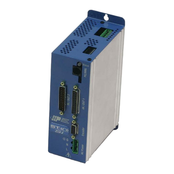
Figure 1.1: STAC6 Applied Motion Products (Motor Control) Thank you for selecting an Applied Motion Products motor control from Tolomatic. We are committed to making your motion control project successful. If there’s anything we can do to help you service or troubleshoot your system. -
Page 15: Getting Started
1: H A R D W A R E Getting Started For all STAC6 Drive models, you must have the following: • 120VAC or 220VAC single phase power • A compatible stepper motor • A small flat blade screwdriver for tightening the connectors (included). -
Page 16: Error Codes / Status Led
1: H A R D W A R E Error Codes / Status LED The STAC6 includes a bi-color (red/green) LED to indicate status. Normal status is indicated by a solid green LED. If the LED changes to red, an error has occurred. The errors are indicated by combinations of red and green "flashes"... -
Page 17: Rs 232 Communications
PC, replace the 7 foot phone cord with a longer one. Do not use cords in excess of 50 feet. Never connect a STAC6 drive to a telephone circuit. It uses the same connectors and cords as telephones and modems, but the voltages are not compatible. - Page 18 Host RS-232 to RS-485 adapters that support the 4-wire interface. 2-wire implementations may require special Host adapters that support STAC6 Drives and Microstepping Motors: User Manual (Discontinued Product) • 1.7 •...
- Page 19 2. Connect the drive TX- to PC RX-. 3. Connect RX+ to TX+. 4. Connect RX- to TX-. 5. Connect GND to GND. Getting and Connecting a RS485 4-wire adapter to your STAC6 Drives and Microstepping Motors: (Discontinued Product) User Manual • 1.8 •...
- Page 20 Usually RS-485 2-wire interfaces are labeled "A" & "B". Getting and Connecting a RS485 2-wire adapter to your PC The RS485 2-wire adapter (Model 485-25E) from Integrity Instruments (800-450-2001) is recommended. adapter drive TX+/RX+ TX-/RX- STAC6 Drives and Microstepping Motors: (Discontinued Product) User Manual • 1.9 •...
- Page 21 %. To test, type %RV. The drive should respond just as it does to RV, the global revision level request. Once all the drives have been assigned unique addresses, you can proceed to wire the whole system. STAC6 Drives and Microstepping Motors: (Discontinued Product) User Manual • 1.10 •...
-
Page 22: Connecting Ac Power
1: H A R D W A R E Wiring Your Drive CONNECTING AC POWER The STAC6 accepts an AC supply voltage from 94 to 135VAC , 50/60Hz. The is a special version designed to [STAC6-Si-220] operate from 94 to 265 VAC. Using the connector supplied and AWG 16 wire, connect to the AC supply as per the diagram below. - Page 23 In most cases, the motor includes a pre-assembled connector for the STAC6. If your motor does not already have a connector attached or the length of the cable needs to be changed, please refer to the illustration below.
-
Page 24: Connecting The Encoder
They are far less sensitive to electrical interference and provide problem free performance. Use of differential encoders with the STAC6 enables the drive to detect a broken wire or bad signal and display an alert. If using single-ended encoders, connect to the A+ and B+ terminals only. - Page 25 Alarm Reset input (see I/O Dialog). Stall Prevention can prevent many stalls before they occur. The STAC6 achieves this by using the encoder to monitor the lead angle of the motor, a measure of torque utilization. If the motion profile begins to demand more torque than the motor can produce, the velocity is automatically reduced before the motor stalls.
- Page 26 In the event that the motor cannot move at all, such as hitting a hard stop, fault the drive after a given amount of time by checking the "Hard Stop" box and entering a time limit. STAC6 Drives and Microstepping Motors: (Discontinued Product) User Manual...
- Page 27 Figure 1.9: Connections In/Out 1 HIGH SPEED DIGITAL INPUTS The STAC6 drives include two high speed inputs called STEP and DIR. They accept 5 volt single-ended or differential signals, up to 2 MHz. These are configured using the STAC6 Configurator software.
- Page 28 Figure 1.10: Step Source – Connecting to indexer with Sourcing Outputs Figure 1.11: Step Sink – Connecting to indexer with Sinking Outputs (includes Applied Motion Si-1 Indexer) Figure 1.12: Step Differential – Connecting to indexer with Differential Outputs STAC6 Drives and Microstepping Motors: User Manual (Discontinued Product) • 1.17 •...
- Page 29 5 volts. Never apply high voltage AC to an input terminal. Figure 1.14: Connecting to PLC with Sourcing (PNP) Outputs (most PLC's use 24 volt logic) STAC6 Drives and Microstepping Motors: (Discontinued Product) User Manual • 1.18 •...
- Page 30 Because the input circuits are isolated, they require a source of power. When connecting to a PLC, the PLC should be able to supply the power. When using relays or STAC6 Drives and Microstepping Motors: (Discontinued Product) User Manual...
- Page 31 Note: If current is flowing into or out of an input, the logic state of that input is low or closed. If no current is flowing, or the input is not connected, the logic state is high or open. STAC6 Drives and Microstepping Motors: (Discontinued Product) User Manual...
- Page 32 1: H A R D W A R E DIGITAL INPUT CONNECTION EXAMPLES Figure 1.18: INP Relay Figure 1.19: Si1 Figure 1.20: INP NPN In/Out 1 Figure 1.21: INP PNP 1 STAC6 Drives and Microstepping Motors: User Manual (Discontinued Product) • 1.21 •...
- Page 33 1: H A R D W A R E CONNECTING LIMIT SWITCHES TO THE STAC6 DRIVE The CWLIM and CCWLIM inputs are used for connecting end-of- travel sensors. These inputs are differential, which allows use of signals that are sinking (NPN), sourcing (PNP) or differential (line driver).
- Page 34 These devices must be wired differently than switches. If an open collector output or a sinking output sensor is used, wire as shown below. Figure 1.24: NPN Limit Sensor STAC6 Drives and Microstepping Motors: (Discontinued Product) User Manual • 1.23 •...
- Page 35 Other sensors have sourcing outputs causing current to flow out of the sensor output, but not into it. Sensors with sourcing outputs should be wired as shown below. Figure 1.25: PNP Limit Sensor STAC6 Drives and Microstepping Motors: User Manual (Discontinued Product) • 1.24 •...
- Page 36 LEDs will flash an error code. Motion: Indicates that the drive has achieved a desired goal, such as a target position. Figure 1.27: STAC6 Outputs STAC6 Drives and Microstepping Motors: (Discontinued Product) User Manual • 1.25 •...
- Page 37 Do not connect the outputs to more than 30VDC. The current through each output terminal must not exceed 100 mA. Figure 1.28: STAC6 Outsinking Figure 1.29: STAC6 Relay STAC6 Drives and Microstepping Motors: (Discontinued Product) User Manual • 1.26 •...
- Page 38 Connecting Analog Inputs on the IN/OUT 1 Connector Figure 1.30: Connections In/Out The STAC6 has a ±10 Volt analog input that can be used by drive for a number of dedicated purposes for controlling motor. It can also be used for general purpose analog input signals.
- Page 39 Connecting an Analog Input to a Potentiometer or Joystick Figure 1.32: Analog Pot STAC6 Drives and Microstepping Motors: (Discontinued Product) User Manual • 1.28 •...
- Page 40 If you are using relays or mechanical switches, a 12-24 V power supply will be required. This also applies when connecting the inputs to the programmable outputs of another Drive. [STAC6-Si] STAC6 Drives and Microstepping Motors: (Discontinued Product) User Manual • 1.29 •...
- Page 41 (PNP) input signals, connect COM to ground (power supply -). When using sinking (NPN) signals, then COM must connect to power supply +. [STAC6-Si] Figure 1.34: Inputs SI [STAC6-Si] STAC6 Drives and Microstepping Motors: (Discontinued Product) User Manual • 1.30 •...
- Page 42 "If Input" instruction. Use a normally open momentary switch for jogging. CONNECTING ANOTHER Si DRIVE Figure 1.36: Output In/Out 2 – When output closes, drive input goes low. STAC6 Drives and Microstepping Motors: (Discontinued Product) User Manual • 1.31 •...
- Page 43 Figure 1.37: NPN Proximity In/Out 2 – When prox. sensor activates, drive input goes low. CONNECT PNP TYPE PROXIMITY SENSOR TO AN INPUT Figure 1.38: PNP Proximity In/Out 2 – When prox. sensor activates, drive input goes low. STAC6 Drives and Microstepping Motors: (Discontinued Product) User Manual • 1.32 •...
- Page 44 OUT 2 connector outputs, both the "+" (collector) and "-" (emitter) terminals of each transistor are available on the connector pins. This allows configuration of each output for current sourcing or sinking. STAC6 Drives and Microstepping Motors: (Discontinued Product) User Manual...
- Page 45 Diagrams of each type of In/Out connection follow. Do not connect the outputs to more than 30VDC. The current through each output terminal must not exceed 100 mA. [STAC6-Si] [STAC6-S] Figure 1.41: Sourcing Out STAC6 Drives and Microstepping Motors: (Discontinued Product) User Manual • 1.34 •...
- Page 46 1: H A R D W A R E [STAC6-Si] [STAC6-S] [STAC6-Si] Figure 1.42 Out Sinking [STAC6-Si] [STAC6-S] [STAC6-Si] Figure 1.43: Relay STAC6 Drives and Microstepping Motors: (Discontinued Product) User Manual • 1.35 •...
- Page 47 Figure 1.44: In/Out 2 Connections CONNECTING TO THE AUX ANALOG INPUT The auxiliary analog input on the STAC6 IN/OUT 2 connector can be used by "Feed to Sensor" commands and other input functions when operating the drive in "Host" mode. The analog input can also be read back to the "Host"...
- Page 48 Connections are shown below. The +5V terminal is an output. Do not connect it to a power supply. Figure 1.45: Connecting an Analog Input to an Active Signal STAC6 Drives and Microstepping Motors: (Discontinued Product) User Manual • 1.37 •...
-
Page 49: Regeneration Clamp
1: H A R D W A R E Regeneration Clamp The STAC6 includes a regeneration clamp circuit and internal power dump resistor. Only the circuit is designed to handle any power level that the drive is able to out put. - Page 50 1: H A R D W A R E Figure 1.47: Regen Resistor Connection Figure 1.48: STAC6 External Regen STAC6 Drives and Microstepping Motors: (Discontinued Product) User Manual • 1.39 •...
-
Page 51: Chapter 2: Recommended Motors
Recommended Motors Applied Motion motors are suited for the use with the STAC6. These motors have been tested and approved by Applied Motion Products and Tolomatic. GENERAL MOTOR DATA Figure 2.1: General Motor Data Table SIZE 23 MOTORS Figure 2.2: Size 23 Motors... -
Page 52: Size 34 Motors
1.766 MRS23 [HT23-550D] 1.412 MRS22 [HT23-549D] MRS21 [HT23-548D] 1.059 .706 .353 REVS PER SECOND Figure 2.3: HT 23 Torque Curves SIZE 34 MOTORS Figure 2.4: Size 34 Motors STAC6 Drives and Microstepping Motors: User Manual (Discontinued Product) • 2.2 •... - Page 53 Ratings are with motor connected in series 1500 10.59 MRS33 [HT34-490D] 1250 8.83 MRS32 [HT34-489D] MRS31 [HT34-488D] 1000 7.06 5.30 3.53 1.77 REVS PER SECOND Figure 2.5: HT 34 Torque Curves STAC6 Drives and Microstepping Motors: (Discontinued Product) User Manual • 2.3 •...
- Page 54 LENGTH "L" DIA."D" MODEL HT23 - 548 43.8 6.35 HT23 - 549 2.16 54.8 6.35 HT23 - 550 3.05 77.5 6.35 Ratings are with motor connected in series STAC6 Drives and Microstepping Motors: User Manual (Discontinued Product) • 2.4 •...
- Page 55 LENGTH "L" DIA."D" MODEL HT34 - 488 3.11 12.7 HT34 - 489 4.63 117.6 12.7 HT34 - 490 6.14 155.9 .625 15.875 Ratings are with motor connected in series STAC6 Drives and Microstepping Motors: (Discontinued Product) User Manual • 2.5 •...
-
Page 56: Chapter 3: Configuration
Configuration STAC6 Configurator Software The Configurator is used to configure a STAC6 drive for your application. The drive set up is divided into six sections, each focusing on one area of configuration. Drop down menus provide additional functionality. Figure 3.1: STAC6 Configurator... - Page 57 3: C O N F I G U R A T I O N DRIVE First, select the appropriate STAC6 model from the configurator drop down list in the upper right corner of the screen. The -S can be used for three types of applications.
- Page 58 REGEN CLAMP A fast moving load can possess considerable kinetic energy especially if it has high rotating mass (inertia). If the STAC6 decelerates that load quickly, much of that kinetic energy is transferred back into the drive electronics. This is called "regeneration."...
-
Page 59: Configuring The Motor
Configuring the Motor Figure 3.2: Motor Dialog The STAC6 works best with the specially matched motors in the Recommended List. To configure the drive for one of these motors, click on the motor icon, select a motor from the drop down list, and set the current. - Page 60 LOAD INERTIA The anti-resonance feature of the STAC6 is most effective when the load inertia is precisely set. If this value is known, click on the first option button, enter the inertia in the box and select the units (oz-in-sec2, g-cm2, etc) from the list.
- Page 61 Above a certain speed, further increases in lead angle produce no benefit, and the STAC6 must be told when to stop advancing the timing. In the example below, the lead angle is increased steadily from 90°...
- Page 62 "135 degrees at 40 rev/sec", as shown. If Stall Prevention is not being used, these values are not needed by the STAC6. Figure 3.4: Lead Angle Graph STAC6 Drives and Microstepping Motors: (Discontinued Product) User Manual • 3.7 •...
-
Page 63: Input And Outputs
The drive features a Fault Output that will be triggered if there is a fault condition. This may be a fault within the drive or it may indicate a system fault. Not all faults will disable the drive. If running the STAC6 Configurator while an alarm condition develops, a dialog box will display providing details of the fault. - Page 64 LIMIT SWITCH INPUTS The STAC6 has two inputs that can be configured as end of travel limit switches. These are useful for linear applications such as actuators.
- Page 65 The Motor Enable Input is used to turn the power stage of the drive on and off. This means the drive can be powered on, but the motor will not be active. STAC6 Drives and Microstepping Motors: (Discontinued Product) User Manual...
-
Page 66: Status Monitor
• Status flags (enabled, motion, jogging, etc.) The motor can be enabled or disabled from the Status Monitor by clicking the buttons at the bottom of the display. STAC6 Drives and Microstepping Motors: (Discontinued Product) User Manual • 3.11 •... -
Page 67: Chapter 4: Standard Accessories & Options
• Screw Terminal Connectors mate directly to the IN/OUT connectors on the front panel of the drive: Phoenix Contact P/N 2761619 (for IN/OUT 2) and 2761622 (for IN/OUT 1). This connector is not available from Tolomatic. You must purchase it from a Phoenix distributor. CABLES AND SURGE PROTECTORS •... -
Page 68: Hub [Sinet™ Hub 444] Multi-Axis Motion Hub With I/O
#1. No external power [SiNET™ HUB 444] supply required. • Controls and powers optional MMI (operator terminal). • Optional DIN rail mounting kit for easy installation. COMPATIBLE INDEXER & DRIVES STAC6 Drives and Microstepping Motors: User Manual (Discontinued Product) • 4.2 •... - Page 69 It also eliminates common problems associated with the set up and programming of a system. Using the SiNet Hub Programmer™ software is recommended before considering Router Mode. STAC6 Drives and Microstepping Motors: (Discontinued Product) User Manual • 4.3 •...
- Page 70 To use the in Router Mode, you will need: [SiNET™ HUB 444] STAC6 Drives and Microstepping Motors: User Manual (Discontinued Product) • 4.4 •...
- Page 71 C, Visual Basic or Labview is required. The sketch below identifies some of the features of [SiNET™ HUB 444] Figure 4.2: HUB [SiNET™ HUB 444] Features STAC6 Drives and Microstepping Motors: (Discontinued Product) User Manual • 4.5 •...
- Page 72 Not following this procedure can seriously damage the hub, the drives, or your PC. If in doubt, purchased cables are highly recommended. Figure 4.3: Connecting the HUB [SiNET™ HUB 444] STAC6 Drives and Microstepping Motors: (Discontinued Product) User Manual • 4.6 •...
- Page 73 ASCII string “1FL” followed by a carriage return (ASCII 13). If you omit the address character, the command is “global” and will be sent to all drives. That is useful is when sending the same parameter STAC6 Drives and Microstepping Motors: User Manual (Discontinued Product)
- Page 74 When running a program from the PC a PIT related instruction executes and a "virtual MMI"will appear on the computer screen demonstrating all the features. STAC6 Drives and Microstepping Motors: (Discontinued Product) User Manual • 4.8 •...
- Page 75 When using a TTL circuit to drive the hub inputs, connect the “+” terminals to the 5 volt bus. No ground connection is needed. If a PLC or proximity sensor is used, a power supply is required. STAC6 Drives and Microstepping Motors: (Discontinued Product) User Manual...
- Page 76 Figure 4.5: Connecting an Si Drive Figure 4.6: Connecting an NPN Type Prox. Sensor Figure 4.7: Connecting a PNP Type Prox. Sensor STAC6 Drives and Microstepping Motors: (Discontinued Product) User Manual • 4.10 •...
- Page 77 Do not connect the outputs to more than 30VDC. The current through each output terminal must not exceed 100 mA. Figure 4.8: Output Circuit Schematic Diagram Figure 4.9: Sinking Output Figure 4.10: Sourcing Output STAC6 Drives and Microstepping Motors: User Manual (Discontinued Product) • 4.11 •...
- Page 78 4: S T A N D A R D A C C E S S O R I E S & O P T I O N S Figure 4.11: Driving a Relay MECHANICAL OUTLINE Figure 4.12: Mechanical Outline STAC6 Drives and Microstepping Motors: User Manual (Discontinued Product) • 4.12 •...
- Page 79 Options: DIN rail mounting kit (DMK-1) Inputs Optically isolated, differential 5-24V logic. 2200 ohms internal resistance. 1.5 mA minimum “on” current. Outputs Optically isolated, darlington photo transistors: 30V, 100 mA max STAC6 Drives and Microstepping Motors: (Discontinued Product) User Manual • 4.13 •...
- Page 80 4: S T A N D A R D A C C E S S O R I E S & O P T I O N S PIN ASSIGNMENTS Figure 4.13: Pin Assignments STAC6 Drives and Microstepping Motors: User Manual (Discontinued Product)
-
Page 81: Chapter 5: Contacting Tolomatic
Contacting Tolomatic Our technical support staff is ready to help you with any questions you may have regarding Tolomatic products. Corporate Headquarters 3800 County Road 116 Hamel, MN 55340 P: 800-328-2174 P: 763-478-8000 F: 763-478-8080 Hours of Operation M-F 7:30 - 5:00 CST Website www.tolomatic.com... - Page 82 3800 County Road 116 Hamel, MN 55340 P: 763.478.8000 F: 763.478.8080 www.tolomatic.com 3600-4645_02_AMPSTEP-OBS...
Need help?
Do you have a question about the STAC6 and is the answer not in the manual?
Questions and answers